
High-gain wideband microstrip patch antenna

A microstrip patch antenna, high-gain technology, applied in antennas, resonant antennas, electrical short antennas, etc., can solve problems such as infeasible solutions, increase array elements to improve gain, etc., to achieve simple implementation, increase array scale, and easy production. Effect

Active Publication Date: 2017-10-03
TONGYU COMM INC
View PDF4 Cites 14 Cited by
  • Summary
  • Abstract
  • Description
  • Claims
  • Application Information

AI Technical Summary

Problems solved by technology

Moreover, for the situation where the size of the micro base station is strictly limited and the gain cannot be increased by adding array elements, the amount of improvement is even greater, which directly determines the feasibility of the solution.

Method used


Image

  • High-gain wideband microstrip patch antenna
  • High-gain wideband microstrip patch antenna
  • High-gain wideband microstrip patch antenna

Examples


Embodiment Construction

[0040] The preferred embodiments of the invention patent are given below in conjunction with the accompanying drawings to describe the technical solution of the present invention in detail. Here, the present invention will be described in detail with reference to the accompanying drawings. It should be noted that the preferred implementation examples described here are only used to illustrate and explain the present invention, and are not used to limit or limit the present invention.

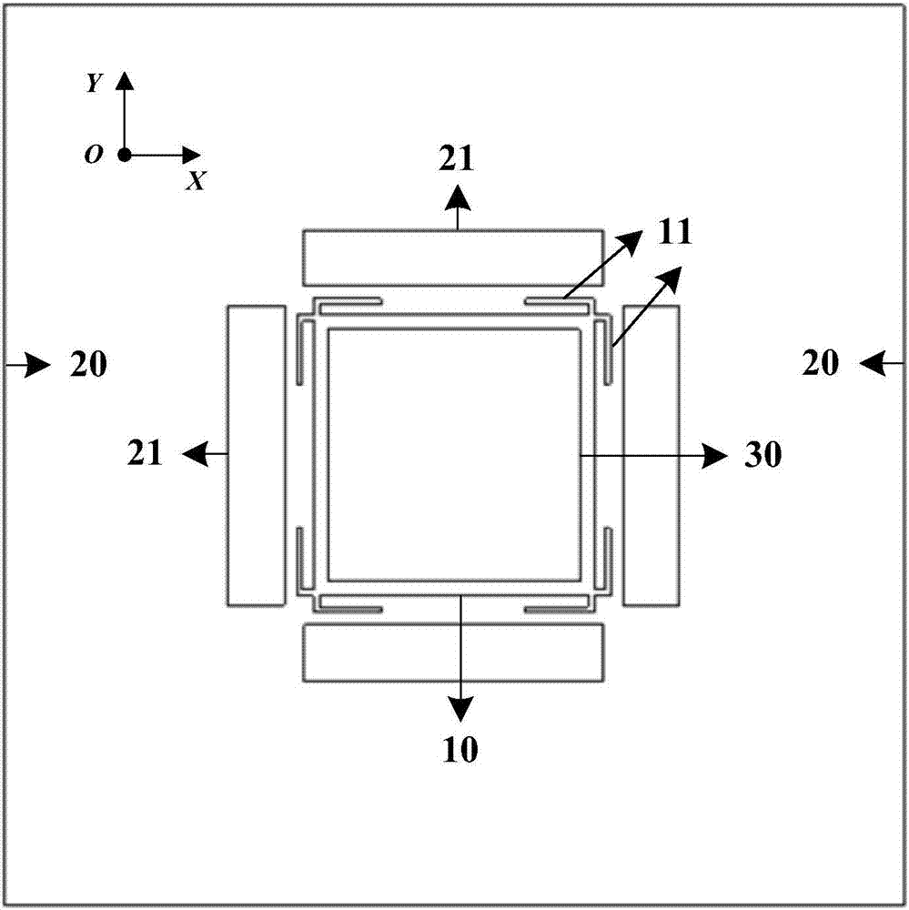
[0041] see Figure 1-9 , in the embodiment of the present invention, the high-gain broadband microstrip patch antenna is constructed as follows:

[0042] Step 1, establish a space Cartesian coordinate system, see figure 1 ;

[0043] Step two, set up the metal floor. On the XOY plane, with the coordinate origin O as the center, construct a side length W g , thickness T g The square metal floor 20 serves as the ground plane for the antenna, see figure 2 ;

[0044] Step 3, set the main rad...


PUM


Abstract

The invention provides a high-gain wideband microstrip patch antenna. The high-gain wideband microstrip patch antenna comprises a floor, a dielectric plate arranged on the floor and a main radiation patch, wherein the main radiation patch is positioned at the position with the distance of Hp above the ground, and is in a rectangular shape; a top parasitism patch is arranged at the position with the distance of Hs above the main radiation patch, and is in the rectangular shape as well; four rectangular horizontal parasitism patches are arranged at the positions with the distances of Dp on the outer side of the peripheral edge of the main radiation patch, the heights of the four rectangular horizontal parasitism patches from the floor are Hc, and the lengths and widths of the four rectangular horizontal parasitism patches are Ls and Ws; and a feeding point is arranged on the main radiation patch, and is connected to a feeding network of the dielectric plate. Namely, a distance is reserved between the main radiation patch and the floor, and a distance is reserved between the top parasitism patch and the main radiation patch. A base station antenna which is high in gain, wide in band, dual in polarization, low in sidelobe or free of sidelobe, high in cross polarization, high in isolation, wide in wave beam, miniaturized, low in profile, low in cost and easy to produce is provided for micro cellular mobile communication.

Description

【Technical field】 [0001] The invention relates to a mobile communication micro-base station antenna device and technology, in particular to a high-gain broadband microstrip patch and its technology. 【Background technique】 [0002] With the continuous increase of network deployment density, mobile communication has basically achieved wide-area continuous coverage of signals. However, limited by the operating frequency band and coverage area, it is difficult for macro cells to meet the requirements of high data transmission rate and large system capacity, and it is also large in size, difficult in site selection, and high in cost. In contrast, micro base stations have the advantages of small size, low profile, easy installation, strong concealment, and low cost, and are suitable for local high-speed data services with dense users. This type of base station antenna generally has the characteristics of medium gain (8-14dBi), wide beam (horizontal beam width of 65°, 90° or above...

Claims


Application Information

Patent Timeline
Patent Type & Authority Applications(China)
IPC IPC(8): H01Q9/04
CPCH01Q9/0414H01Q9/045
Inventor 李道铁吴中林刘木林
Owner TONGYU COMM INC
Learn More