Eureka AIR delivers breakthrough ideas for toughest innovation challenges, trusted by R&D personnel around the world.

Liquid-gas coexistence type buffering device and buffering device array

A buffer device and liquid-gas technology, applied in the direction of gas-liquid shock absorbers, springs, shock absorbers, etc., can solve the problems of increasing the degree of injury to people inside the vehicle, making it difficult to protect the life safety of the vehicle, and reducing the impact force of impacts, etc., to achieve Increase the scope of application, increase the scope and flexibility of application, and reduce the effect of destructive force

Inactive Publication Date: 2017-10-03
周满阳
View PDF7 Cites 1 Cited by
  • Summary
  • Abstract
  • Description
  • Claims
  • Application Information

AI Technical Summary

Problems solved by technology

But both devices have significant limitations:
[0005] 1. The bumper is a kind of hard collision device, which only reduces the degree of damage to the front of the vehicle (and other sports tools, the same below, and will not repeat it), but does not reduce the impact force for the entire impact, that is, after the impact, the impact on the entire The injury of the vehicle and the personnel inside the vehicle has not been reduced, and basically has no protective effect; the bumper may even increase the degree of injury to the personnel inside the vehicle. The bumper is a hard collision protection device, which will reduce the time of the collision process and form a stronger Hard collision situations, that is, although the bumper can protect the integrity of the front of the vehicle to a certain extent, it will actually cause more damage to the occupants of the vehicle
[0006] 2. The entire process of airbag explosion activation has a time lag. It is often after the second collision of the human body that the gas formed by the airbag explosion is generated, that is, the rescue is often "started after being injured", and the impact of the airbag explosion Force can cause new damage to personnel
Therefore, the anti-collision equipment combined with the bumper and the airbag is often difficult to protect the safety of the people on the vehicle, and countless accidents have proved this point

Method used


Image

  • Liquid-gas coexistence type buffering device and buffering device array
  • Liquid-gas coexistence type buffering device and buffering device array
  • Liquid-gas coexistence type buffering device and buffering device array

Examples


Embodiment 1

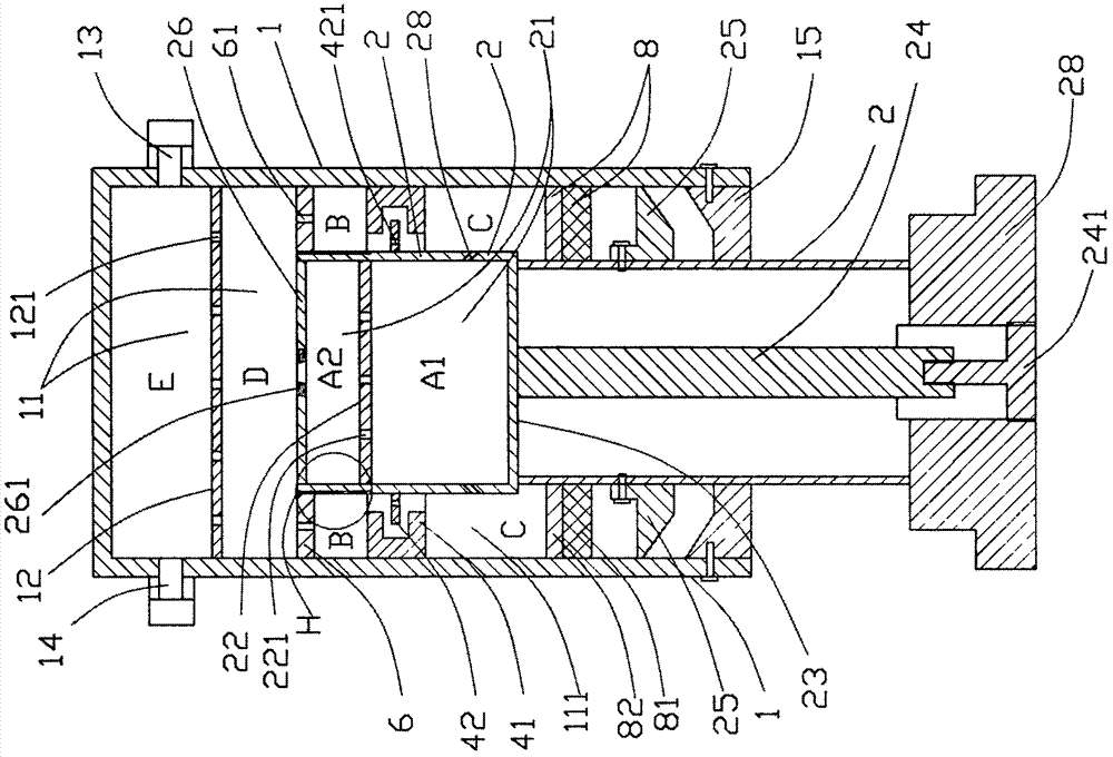
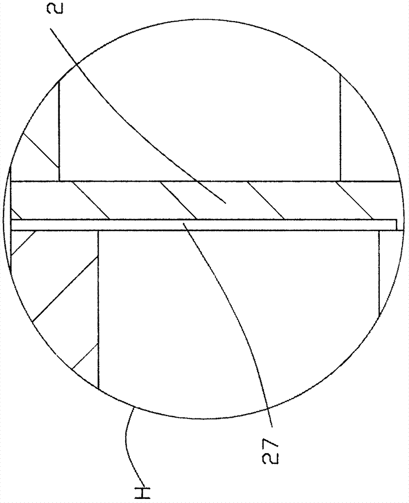
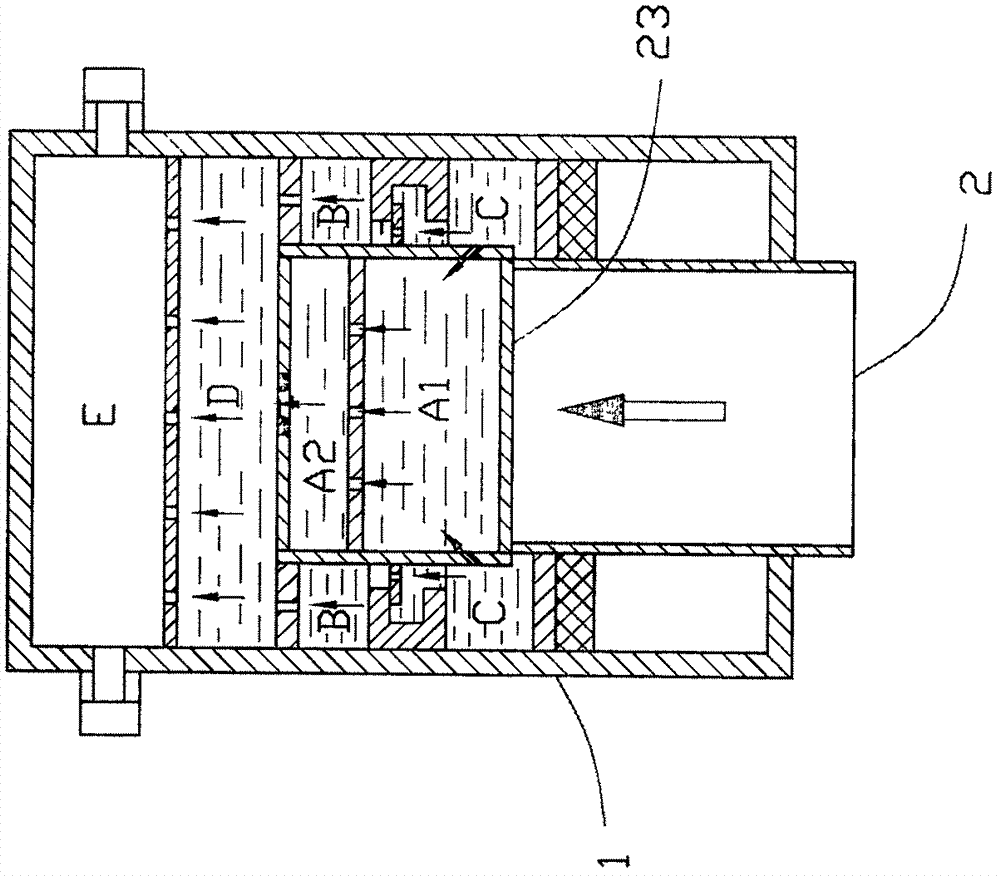
[0037] Such as Figure 1-2 As shown, a buffer device for coexistence of liquid and gas includes an outer cylinder 1 and an inner cylinder 2, and the outer cylinder 1 and the inner cylinder 2 are in a cylindrical structure as a whole (that is, have an outer wall and a bottom plate, and an inner cavity with an opening ), the outer cylinder 1 is provided with an outer cylinder cavity 11 for containing buffer liquid and gas and installing the inner cylinder 2, and the outer cylinder cavity 11 is divided into a gas cavity (such as figure 1Shown E chamber) and liquid chamber (D chamber); Inner cylinder 2 is provided with the inner cylinder lumen 21 that is used for containing buffered liquid.

[0038] On the outer cylinder 1, an outer cylinder restrictor plate 12 (can be more than one) is fixedly installed in the inner cavity 11 of the outer cylinder, and the outer cylinder restrictor plate 12 is used to control the speed at which the buffer liquid flows from the liquid chamber to t...

Embodiment 2

[0053] Such as Figure 4-5 As shown, a buffer device for the coexistence of liquid and gas includes an outer cylinder 1 and an inner cylinder 2. Both the outer cylinder 1 and the inner cylinder 2 have a cylindrical structure as a whole. The outer cylinder inner cavity 11 of the inner cylinder 2, the outer cylinder inner cavity 11 is divided into a gas cavity (such as figure 1 Shown E chamber) and liquid chamber (D chamber); Inner cylinder 2 is provided with the inner cylinder lumen 21 that is used for containing buffered liquid.

[0054] The main difference between it and Embodiment 1 is that the outer tube restrictor plate 12 is curled into a tubular shape, and one end thereof is installed on the bottom plate of the outer tube 1; the inner piston 26 is installed on the other end of the outer tube restrictor plate 12, and the outer circumference of the inner piston 26 is The inner wall of the inner cylinder 2 is movably socketed, that is, the inner piston 26 is movably sleeve...

Embodiment 3

[0056] Such as Figure 6 Shown, a kind of buffer device array that liquid gas coexists, by two (or more than two) embodiment 1 (as Figure 6 shown) or embodiment 2 (the accompanying drawings do not show this combination structure), two or more buffer devices are arranged side by side and connected as a whole, specifically it may be: Also comprise public base 16 and public anti-collision beam 17, the bottom plate of the outer tube 1 of each buffer device is all connected on the common base 16, and the impact protection plate 28 of the outer tube 1 of each buffer device is all connected on the public anti-collision beam 17 The public anti-collision beam 17 is provided with an air bag 18; the cascading nozzles 13 of the outer cylinder 1 of each buffer device are connected in turn, so that the pressure is balanced during the collision, and the shrinkage of the inner cylinder 1 can be consistent.

[0057]The outer cylinder 1 at both ends of the buffer device array is symmetrically...


PUM


Abstract

The invention discloses a liquid-gas coexistence type buffering device. The liquid-gas coexistence type buffering device comprises an outer cylinder (1) and an inner cylinder (2). An outer cylinder inner cavity (11) used for containing buffering liquid and gas and mounting the inner cylinder (2) is formed in the outer cylinder (1). One or more outer cylinder flow limiting plates (12) are mounted on the outer cylinder (1) and located in the outer cylinder inner cavity (11). The outer cylinder inner cavity (11) is divided into a plurality of buffering chambers by the outer cylinder flow limiting plates (12). When the liquid-gas coexistence type buffering device is in use, at least one buffering chamber is filled with gas, and channels for liquid or / and gas circulation are formed in the outer cylinder flow limiting plates (12). One end of the inner cylinder (2) is movably mounted in the outer cylinder inner cavity (11) of the outer cylinder (1) in a sleeved mode. The inner cylinder (2) can move in the outer cylinder inner cavity (11) of the outer cylinder (1) in the axial direction. The liquid-gas coexistence type buffering device is wide in application range and flexible in use and can evenly distribute collision stress when collision occurs, prolong the interaction time during collision and achieve an excellent buffering effect.

Description

technical field [0001] The present invention relates to the technical field of buffer devices, in particular to a buffer device and a buffer device array that can effectively prolong the interaction time of impacts in the direction of motion and thus play an excellent buffering role in coexistence of liquid and gas. Background technique [0002] With the development of science and technology, people's living standards continue to improve. Modern tools such as cars, elevators, and object transport lifts that replace people's transportation or reduce labor intensity have entered people's daily lives, bringing great benefits to people's daily travel and work. Great convenience, but also promote the rapid development of all walks of life. [0003] However, cars, elevators, etc. are running faster and have greater inertia, and because of human subjective factors and failures of electromechanical components, accidents such as collisions with other objects often occur, while cars, ...

Claims


Application Information

Patent Timeline
Patent Type & Authority Applications(China)
IPC IPC(8): F16F9/06F16F9/348F16F9/43
CPCF16F9/062F16F9/068F16F9/348F16F9/435
Inventor 周满阳周道军
Owner 周满阳
Why Eureka
Eureka Blog
Learn More