
Conjoined wind-resistance greenhouse

A conjoined and shed technology, which is applied in greenhouse cultivation, climate change adaptation, gardening, etc., can solve the problems of poor grip between the support rod and the ground, unsatisfactory, difficult to withstand the invasion of strong winds, etc., to achieve stable connection, Better grip and better resistance to strong winds

Inactive Publication Date: 2017-10-03
李玲
View PDF0 Cites 2 Cited by
  • Summary
  • Abstract
  • Description
  • Claims
  • Application Information

AI Technical Summary

Problems solved by technology

[0003] 1. In the prior art: due to the defect of its own frame structure, it is difficult to withstand the attack of strong wind in the case of strong wind when it is used. The level of wind is not good enough to meet the requirements of the existing technology
[0004] 2. In the prior art: when in use, due to its insufficient frame structure, when the conjoined greenhouse is exposed to the wind, the part of its own force will be transferred to the middle support rod, and the support rods on both sides are in contact with the ground. The ability to grip the ground is poor and cannot meet the needs of existing technologies

Method used


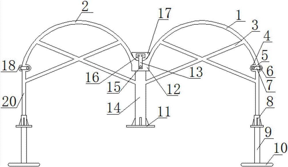
Image

  • Conjoined wind-resistance greenhouse
  • Conjoined wind-resistance greenhouse

Examples


Embodiment Construction

[0017] The following will clearly and completely describe the technical solutions in the embodiments of the present invention with reference to the accompanying drawings in the embodiments of the present invention. Obviously, the described embodiments are only some, not all, embodiments of the present invention. Based on the embodiments of the present invention, all other embodiments obtained by persons of ordinary skill in the art without making creative efforts belong to the protection scope of the present invention.

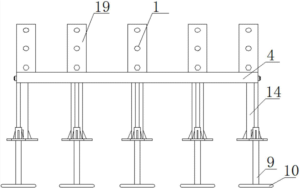
[0018] see Figure 1-2 , the present invention provides a technical solution: a one-piece wind-resistant greenhouse, including a first shed body 1, a second shed body 2, a fixing member 4 and a threaded rod 8, the first shed body 1 and the second shed body The adjacent end of the body 2 is fixedly connected with a connecting plate 12, and the upper surface of the connecting plate 12 is fixedly connected with a plurality of first shed bodies 1 and second shed b...


PUM


Abstract

The invention discloses a conjoined wind-resistance greenhouse. The conjoined wind-resistance greenhouse comprises a first greenhouse body, a second greenhouse body and fixing parts. A connection plate is fixedly connected to adjacent ends of the first greenhouse body and the second greenhouse body, a stress supporting rod is fixedly connected to the bottom end of the connection plate, second connection parts are fixedly connected to two ends of the connection plate through third fixing nuts respectively, the other end of each first connection part is fixedly connected with a second pressure rod through a second fixing nut, a threaded sleeve rod is in threaded connection with the bottom end of each side supporting rod, and cross supporting rods are fixedly connected to inner sides of the first greenhouse body and the second greenhouse body respectively. Since the cross supporting rods are fixedly connected to inner sides of the first greenhouse body and the second greenhouse body respectively, the stress supporting rod is fixedly connected to the bottom end of the connection plate, and fixing rods are fixedly connected to bottom ends of the threaded sleeve rods, ground gripping effects of two ends of the greenhouse in use under a gale condition are better; owing to supporting of the stress supporting rod, stress bearing capacity under the gale condition is increased; by the cross supporting rods, the greenhouse bodies are less prone to deformation, and the greenhouse is capable of effectively withstanding gale attack.

Description

technical field [0001] The invention relates to the technical field of wind-resistant greenhouses, in particular to a one-piece wind-resistant greenhouse. Background technique [0002] With the emergence of high molecular polymers - polyvinyl chloride and polyethylene, plastic films are widely used in agriculture. In the early 1950s, Japan, European and American countries successfully applied greenhouse films to cover hotbeds, and then covered small sheds and greenhouses with good results. my country introduced polyvinyl chloride agricultural film in the autumn of 1955. It was first used to cover vegetables in small sheds in Beijing, and achieved the effect of early maturity and increased production. The greenhouse was originally a special equipment for vegetable production. With the development of production, the application of greenhouses has become more and more extensive. At present, greenhouses have been used for potted flower and cut flower cultivation; fruit tree pr...

Claims


Application Information

Patent Timeline
IPC IPC(8): A01G9/14A01K1/00A01K31/00A01K61/00A01K67/04
CPCA01G9/14A01K1/00A01K31/00A01K61/00A01K67/04Y02A40/25Y02A40/81
Inventor 李玲
Owner 李玲
Learn More