Sharing clothes dryer based on internet of things
A technology of clothes dryer and Internet of Things, which is applied to other washing machines, control devices of washing machines, coin-operated equipment for distributing discrete items, etc. problem, to achieve the effect of smooth switching, preventing clothing loss, and quick response
- Summary
- Abstract
- Description
- Claims
- Application Information
AI Technical Summary
Problems solved by technology
Method used
Image
Examples
Embodiment 1
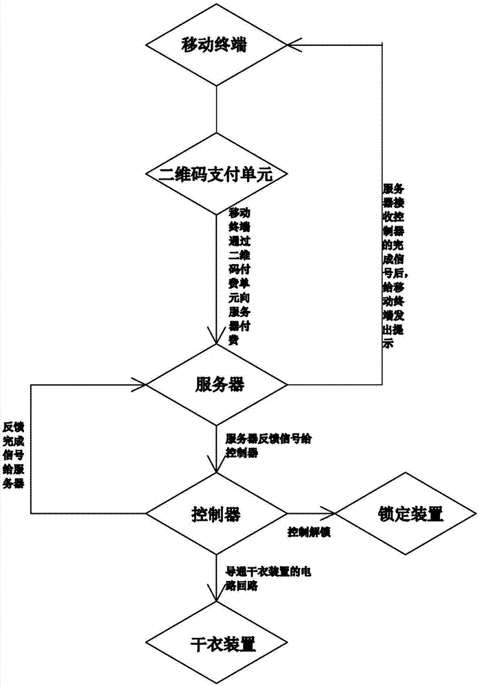
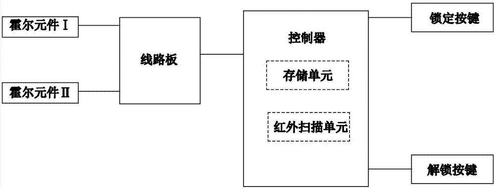
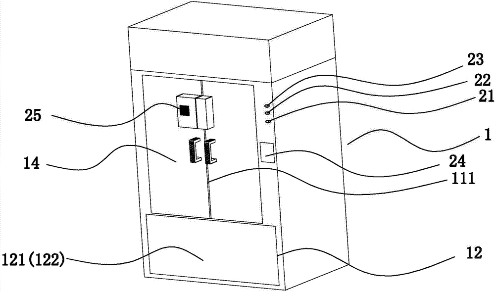
[0036] Refer to attached Figure 1-8 As shown, a shared clothes dryer based on the Internet of Things includes a server and a clothes dryer. The clothes dryer includes a housing 1 on which a two-dimensional code payment unit 25 and an operation button 23 are arranged; Chamber 11, wireless communication unit, clothes drying device, placement chamber 12 and controller; the controller also includes a lock button 21, an unlock button 22, an infrared scanning unit 24, a GPS positioning unit, an alarm unit and a storage unit.
[0037] The server is configured to generate a signal to feed back to the controller by receiving payment information from the mobile terminal.
[0038] Two-dimensional code payment unit 25, the mobile terminal pays to the server by scanning the two-dimensional code payment unit 25.
[0039] The running button 23 is used to control the start and stop of the clothes drying device.
[0040] The controller is used for receiving the feedback signal from the serv...
Embodiment 2
[0056] Refer to attached Figure 9 As shown, the difference between the second embodiment and the first embodiment is that the functions of the micro switch I 141 , the micro switch II 142 and the push rod 136 replace the functions of the magnet and the Hall element. The specific structure is that the locking part 131 is provided with a micro switch I141, and the locking hole 139 is provided with a micro switch II142; the pressing part of the micro switch I141 and the pressing part of the micro switch II142 are both on the sliding track of the push rod; The push rod 136 corresponding to the action switch I141 is in the unlocked position. When the push rod 136 is in the unlocked position, it just touches the pressing part of the micro switch I 141. The micro switch II 142 corresponds to the push rod 136 in the locked position. When the push rod 136 is in the locked position Just touch the pressing part of the micro switch II142; when the pressing part of the micro switch I141 a...
Embodiment 3
[0058] Refer to attached Figure 10-11 As shown, the difference between Embodiment 2 and Embodiment 1 is that the motor 134 is a motor 134 that rotates in one direction. The locking device 13 includes a locking part 131 and a matching part 132. The locking part 131 is located on the movable end of the left end cover plate, and the matching part 132 is located on the movable end of the other cover plate; the locking part 131 is provided with a circuit board 133, The motor 134 and the cam 143, the circuit board 133 are controlled by the controller to drive the motor 134 to rotate in one direction, the cam 143 and the output shaft of the motor 134 are fixed, and the motor 134 drives the rotation to extend and retract the locking part 131; the matching part 132 is provided with a locking hole 139, the cam 143 extends out of the locking part 131 and then extends into the locking hole 139 to lock the two cover plates; the cam 143 is provided with a magnet 137, and the circuit board ...
PUM
 Abstract
Description
Claims
Application Information
 - R&D
- Intellectual Property
- Life Sciences
- Materials
- Tech Scout
- Unparalleled Data Quality
- Higher Quality Content
- 60% Fewer Hallucinations
Browse by: Latest US Patents, China's latest patents, Technical Efficacy Thesaurus, Application Domain, Technology Topic, Popular Technical Reports.
© 2025 PatSnap. All rights reserved.Legal|Privacy policy|Modern Slavery Act Transparency Statement|Sitemap|About US| Contact US: help@patsnap.com


