


Quick Research
Generate reliable direction feasibility study reports for your R&D in just a few steps.

Technical Q&A
Discover and master advanced knowledge NOW. Basics, ideas, possibilities, all at once.

Find Solutions
As an expert in R&D theories, this can generate solutions to your technical problems instantly.

Evaluate Feasibility
Analyze your overall solution with one click, know your potential R&D risks in advance.

Monitor Landscape
Get weekly tech updates, stay abreast of the latest tech innovations and key insights.
Active discharge system of motor controller
A motor controller and active technology, applied in electrical components, output power conversion devices, and AC power input to DC power output, etc., can solve the problem of large voltage change rate current change rate, IGBT easily damaged, and increased hardware circuit costs. and other problems, to achieve the effect of reducing the voltage change rate and current change rate, and reducing the cost
- Summary
- Abstract
- Description
- Claims
- Application Information
AI Technical Summary
Problems solved by technology
Method used
Image

Examples
Embodiment 1
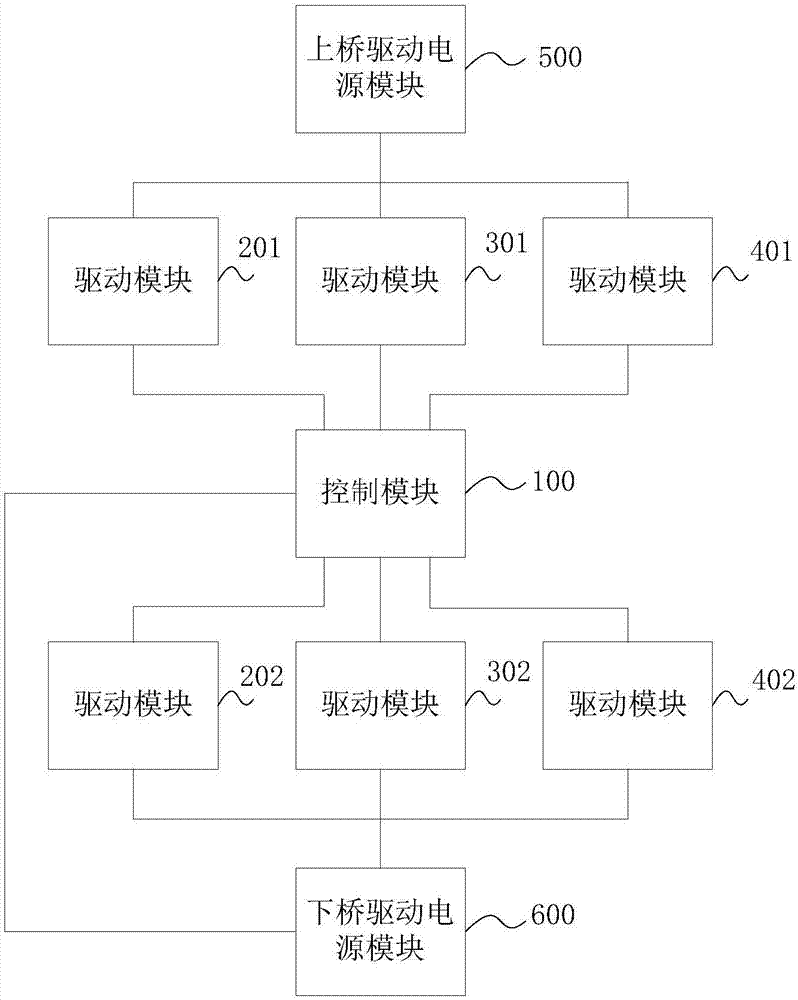
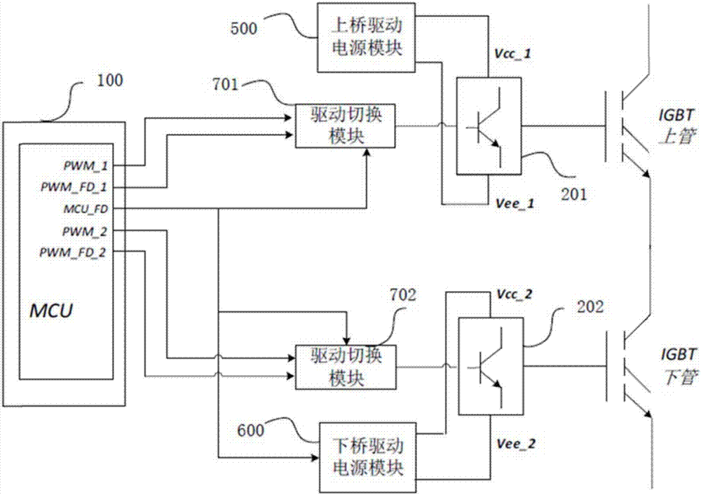
[0051] combine figure 1 ,refer to figure 2 , the active discharge system of the motor controller in Embodiment 1 includes: a control module 100, a plurality of drive modules 201, 202, 301, 302, 401, 402 ( figure 2 The driving modules corresponding to the remaining two-phase bridge arms are not shown), the upper bridge driving power module 500, the lower bridge driving power module 600, and the driving switching modules 701 and 702 corresponding to the driving modules 201 and 202. It can be understood that, because This embodiment only shows the active short-circuit scheme realized by one-phase bridge arm, so only two drive switching modules need to be designed, and in fact, it can also be extended to the active short-circuit scheme realized by two-phase or three-phase bridge arm, only need to add the corresponding The number of drive switching modules is sufficient.
[0052] Wherein, the two input ends and one control end of the drive switching modules 701, 702 are respect...
Embodiment 2
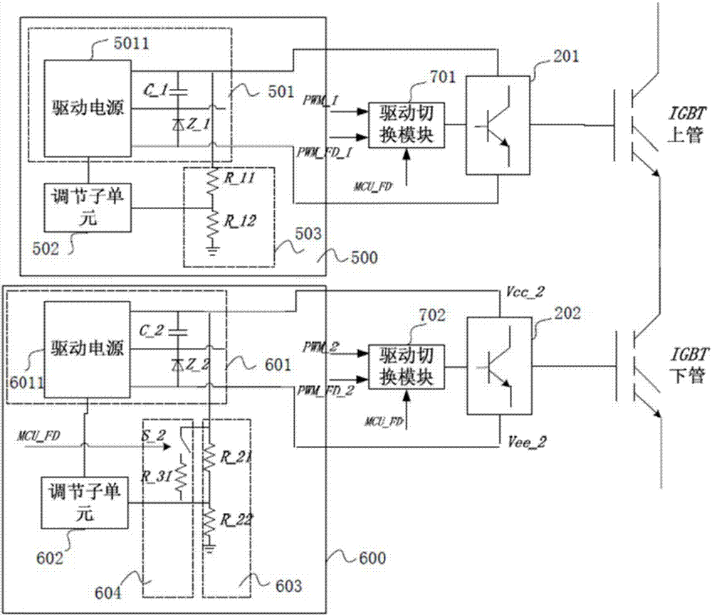
[0063] refer to image 3 , both the upper bridge drive power supply module 500 and the lower bridge drive power supply module 600 specifically include: a drive power supply unit and a feedback adjustment unit. Wherein, the feedback adjustment unit of the lower bridge drive power supply module 600 is also connected to the control module 100, and the control module 100 triggers the feedback adjustment unit of the lower bridge arm to reduce the output by increasing the sampling voltage or reducing the set reference value when active discharge is required. Voltage.
[0064] Specifically, the feedback adjustment unit specifically includes: a voltage sampling subunit and an adjustment subunit. The drive power supply unit includes a drive power supply, an energy storage module, and a voltage stabilizing module. The first end of the energy storage module is connected to the positive power supply terminal, and the second end of the energy storage module is connected to the negative po...
Embodiment 3
[0075] refer to Figure 4 Compared with the second embodiment, the third embodiment differs in that the voltage boosting subunit 604 is connected in parallel with the second sampling resistor R_22, and the voltage boosting subunit 604 includes a second controllable switch S_3 and a second controllable switch S_3 connected in series. Two adjustment resistors R_32, the control terminal of the second controllable switch S_3 is connected to the control module 100, and the control module 100 triggers the switching of the second controllable switch S_3 from the on state to the off state when active discharge is required .
[0076] The principle of reducing the output voltage of the lower bridge drive power module in this embodiment: When active discharge is required, the MCU sends the MCU_FD signal, the switch S_3 is turned on, and the resistor R_32 is no longer connected to the circuit, causing the current of the current resistor R_22 to become larger and sent to The sampling volt...
PUM
 Abstract
Description
Claims
Application Information
 - R&D Engineer
- R&D Manager
- IP Professional
- Industry Leading Data Capabilities
- Powerful AI technology
- Patent DNA Extraction
Browse by: Latest US Patents, China's latest patents, Technical Efficacy Thesaurus, Application Domain, Technology Topic, Popular Technical Reports.
© 2024 PatSnap. All rights reserved.Legal|Privacy policy|Modern Slavery Act Transparency Statement|Sitemap|About US| Contact US: help@patsnap.com