
Automatic electrolyte injection equipment

An electrolyte and liquid injection technology, applied in circuits, electrical components, battery pack components, etc., can solve the problems of low degree of automation, low injection efficiency, low production capacity, etc., and achieve high degree of automation, time saving and high efficiency Effect

Pending Publication Date: 2017-09-22
SHENZHEN YUCHEN AUTOMATION EQUIP CO LTD
View PDF20 Cites 15 Cited by
  • Summary
  • Abstract
  • Description
  • Claims
  • Application Information

AI Technical Summary

Problems solved by technology

[0006] The purpose of the present invention is to provide an automatic electrolyte injection device to solve the defects of low automation, low injection efficiency and low production capacity in the prior art.

Method used


Image

  • Automatic electrolyte injection equipment
  • Automatic electrolyte injection equipment
  • Automatic electrolyte injection equipment

Examples


Embodiment Construction

[0037] In order to make the technical problems, technical solutions and beneficial effects to be solved by the present invention clearer, the present invention will be further described in detail below in conjunction with the accompanying drawings and embodiments. It should be understood that the described embodiments are some, not all, embodiments of the present invention. Based on the described embodiments of the present invention, all other embodiments obtained by persons of ordinary skill in the art without creative efforts shall fall within the protection scope of the present invention.

[0038] In order to enable those skilled in the art to better understand the technical solutions of the present invention, the implementation of the present invention will be described in detail below in conjunction with specific drawings.

[0039] For the convenience of description, the "front", "rear", "left", "right", "upper" and "lower" referred to in the following are consistent with...


PUM


Abstract

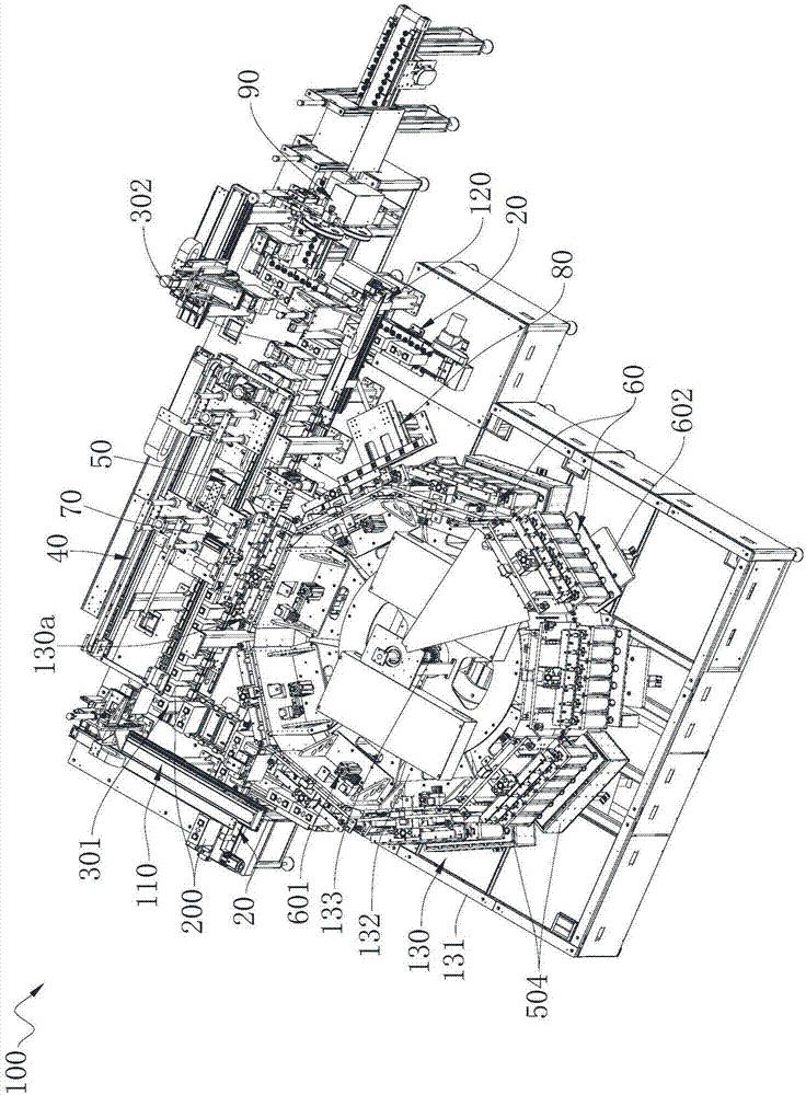
The invention relates to the technical field of battery electrolyte injection, and provides automatic electrolyte injection equipment. The automatic electrolyte injection equipment comprises a first caching apparatus, a second caching apparatus, a feeding apparatus, a discharging apparatus, a rotation apparatus, a plurality of battery electrolyte injection apparatuses, a battery transferring apparatus and a material inlet and outlet apparatus; the rotation apparatus comprises a rack with a material feeding and discharging station, a rotary plate rotationally supported on the rack and a rotary plate power part used for driving the rotary plate to rotate; each battery electrolyte injection apparatus comprises an electrolyte injection supporting base, an electrolyte injection up and down movement mechanism for lifting the electrolyte injection supporting base, and a plurality of electrolyte injection cups arranged on the electrolyte injection supporting base and used for performing electrolyte injection for batteries; and the multiple battery electrolyte injection apparatuses are distributed in the circumferential direction of the rotary plate in sequence. Compared with the prior art, the automatic electrolyte injection equipment provided by the invention can ensure complete absorption of electrolyte and save time, and also has the advantages of high efficiency, high automatic degree and the like.

Description

technical field [0001] The invention relates to the technical field of battery liquid injection, in particular to an automatic electrolyte liquid injection device. Background technique [0002] In the traditional liquid injection production of lithium batteries, the liquid injection hole of the battery box is small, and only manual liquid injection can be used for one-to-one liquid injection processing. Therefore, the production and processing efficiency is low and there are potential safety hazards. [0003] At present, for the traditional manual liquid injection method, the most widely used automatic liquid injection machine is to vacuumize and inject electrolyte. However, the current automatic liquid injection machine still has the following shortcomings: [0004] 1. After the liquid injection cup is vacuumed, the space is large and the vacuuming speed is slow, the vacuum value is not high, and the production efficiency is low. [0005] 2. After the cell is vacuumed and ...

Claims


Application Information

Patent Timeline
IPC IPC(8): H01M2/36
CPCH01M50/60H01M50/691Y02E60/10
Inventor 袁纯全
Owner SHENZHEN YUCHEN AUTOMATION EQUIP CO LTD
Learn More