Multi-station filter leakage detection device
A filter and multi-station technology, applied in the direction of detecting the appearance of fluid at the leakage point, using liquid/vacuum degree for liquid tightness measurement, etc., can solve the problem that the detection effect is not obvious enough, the detection efficiency is low, and the detection Single method and other problems, to achieve the effect of easy large-scale promotion, simple structure, and obvious detection effect
- Summary
- Abstract
- Description
- Claims
- Application Information
AI Technical Summary
Problems solved by technology
Method used
Image
Examples
Embodiment 1
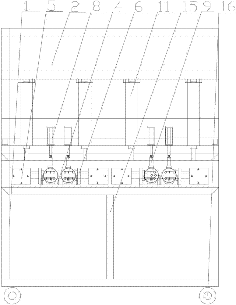
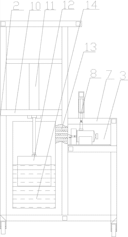
[0017] Such as figure 1 , figure 2 As shown, a multi-station filter leak detection device, the main body includes a base 1, a box 2 is installed on the rear side of the base 1, an open groove 3 is arranged on the base 1, and the inside of the open groove 3 is set There are multiple sets of concave grooves 4 with openings facing upwards. Horizontal limit cylinders 5 are arranged on both sides of the concave grooves 4, and horizontal clips 6 are arranged at the ends of the horizontal limit cylinders 5, and a positioning plate is arranged on the top of the open grooves 3. 7. A vertical cylinder 8 passing through the positioning plate 7 is installed on the positioning plate 7, a top clip 9 is installed at the end of the vertical cylinder 8, a partition 10 is arranged in the middle of the box body 2, and an inverted and There is a water injection cylinder 11 passing through the partition from top to bottom, a floating block 12 is installed at the end of the water injection cylind...
Embodiment 2
[0019] Such as figure 1 , figure 2 As shown, a multi-station filter leak detection device, the main body includes a base 1, a box 2 is installed on the rear side of the base 1, an open groove 3 is arranged on the base 1, and the inside of the open groove 3 is set There are multiple sets of concave grooves 4 with openings facing upwards. Horizontal limit cylinders 5 are arranged on both sides of the concave grooves 4, and horizontal clips 6 are arranged at the ends of the horizontal limit cylinders 5, and a positioning plate is arranged on the top of the open grooves 3. 7. A vertical cylinder 8 passing through the positioning plate 7 is installed on the positioning plate 7, a top clip 9 is installed at the end of the vertical cylinder 8, a partition 10 is arranged in the middle of the box body 2, and an inverted and There is a water injection cylinder 11 passing through the partition from top to bottom, a floating block 12 is installed at the end of the water injection cylind...
PUM
 Abstract
Description
Claims
Application Information
 - R&D Engineer
- R&D Manager
- IP Professional
- Industry Leading Data Capabilities
- Powerful AI technology
- Patent DNA Extraction
Browse by: Latest US Patents, China's latest patents, Technical Efficacy Thesaurus, Application Domain, Technology Topic, Popular Technical Reports.
© 2024 PatSnap. All rights reserved.Legal|Privacy policy|Modern Slavery Act Transparency Statement|Sitemap|About US| Contact US: help@patsnap.com


