Range hood

A technology for range hoods and fans, which is applied to the removal of oil fumes, household stoves/stoves, heating methods, etc. It can solve the problems of reduced effect of range hoods, damage to the negative pressure distribution of fume collection hoods, and inability to greatly improve the suction rate of range hoods, etc. , to achieve the lifting effect and the effect of increasing the central negative pressure area

Active Publication Date: 2017-09-22
NINGBO FOTILE KITCHEN WARE CO LTD
View PDF1 Cites 4 Cited by
  • Summary
  • Abstract
  • Description
  • Claims
  • Application Information

AI Technical Summary

Problems solved by technology

Although the above-mentioned range hood equipped with a cross-flow fan has the above-mentioned advantages, this energy-saving and environmentally friendly high-efficiency side-suction range hood is only suitable for occasions where a rectifying plate is not installed in the fume hood. Installing a cross-flow fan on the edge of the fume hood not only cannot greatly improve the suction rate of the range hood, but will destroy the negative pressure distribution under the fume collection hood, resulting in a decline in the fume suction effect

Method used


Image

  • Range hood
  • Range hood
  • Range hood

Examples


Embodiment 1

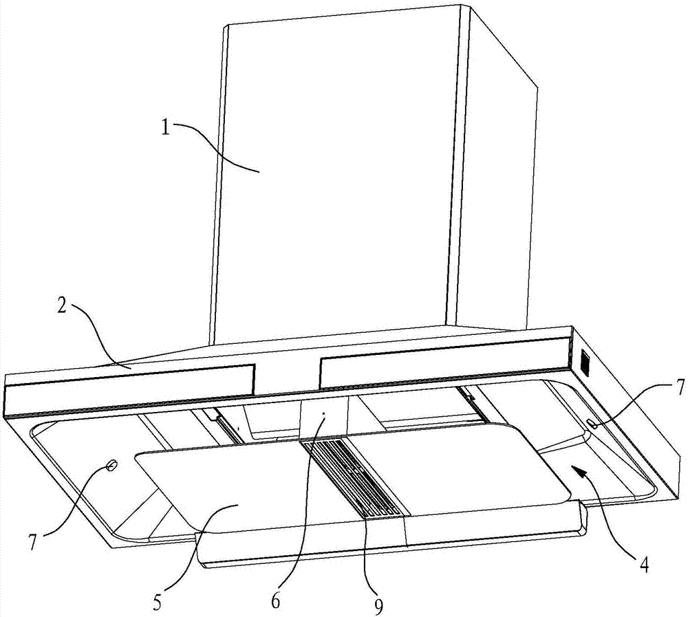
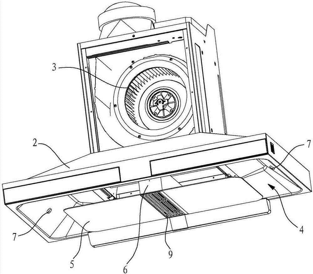
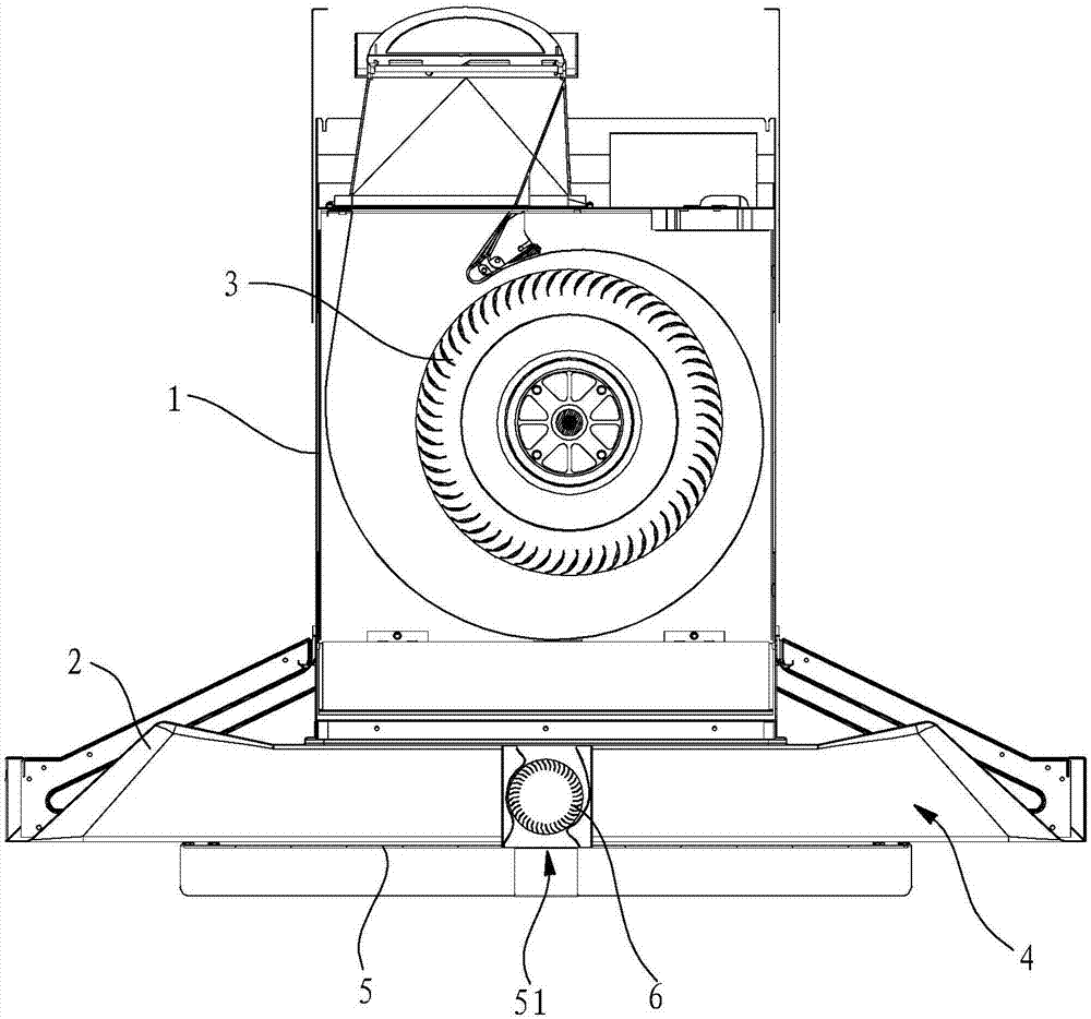
[0021] Such as Figure 1 to Figure 4 As shown, the range hood in this embodiment is a single-fan range hood, which includes a fan housing 1, a smoke collection hood 2, a main fan 3 and a rectifying plate 5, wherein the main fan 3 has one and is installed on Inside the fan housing 1, the main fan 3 is a centrifugal fan. The smoke collecting hood 2 is located below the fan housing 1, and a rectifying chamber 4 is formed below the fume collecting hood 2, and a rectangular rectifying plate 5 is installed in the rectifying chamber 4. The above-mentioned installation structure is the same as that of the existing range hood and will not be described in detail.

[0022] The range hood in this embodiment also includes a cross-flow fan 6, a smoke sensor 7 and a controller (not shown in the figure), and a strip-shaped air inlet 51 is opened in the middle of the rectifying plate 5, and the strip-shaped air inlet 51 is distributed in front and back , that is, the length direction of the s...

Embodiment 2

[0026] Such as Figure 5 and Figure 6 As shown, compared with the first embodiment, the range hood in this embodiment has a main fan 3 added in the fan housing 1, which constitutes a dual-fan range hood. The two main fans 3 are arranged in parallel and are respectively located on the left and right sides directly above the cross-flow fan 6 , and the central axes of the two main fans 3 and the central axis of the cross-flow fan 6 are parallel to each other. An air outlet cover 8 is installed on the fan housing 1 , the planes where the air inlet ends of the two main fans 3 are located are located on the same vertical plane, and the air outlets of the two main fans 3 are connected on the air outlet cover 8 .

[0027] The working principle of the double-fan range hood to improve the effect of the range hood through the cross-flow fan is the same as that of the single-fan range hood in Embodiment 1, and will not be further described here.


PUM


Abstract

The invention discloses a range hood. The range hood comprises a fan housing, an exhaust fume collecting hood and a rectifying plate. The range hood is characterized in that the range hood further comprises a cross-flow fan; a strip-shaped air inlet which is distributed in the front-back direction is formed in the middle of the rectifying plate, and the cross-flow fan is mounted at the strip-shaped air inlet; and the strip-shaped air inlet serves as an air inlet of the cross-flow fan, and an air outlet of the cross-flow fan is located above the rectifying plate. Compared with the prior art, the range hood has the advantages that the strip-shaped air inlet is formed in the middle of the rectifying plate, and the cross-flow fan is additionally arranged at the air inlet for increasing the negative pressure, so that the central negative pressure area is enlarged under the condition that the circumferential negative pressure of the rectifying plate is not weakened, the range hood can have a large fume control area and can also rapidly suck cooking fume, and the cooking fume suction effect is effectively improved accordingly.

Description

technical field [0001] The invention relates to a range hood. Background technique [0002] For the existing range hood with a rectifying plate, under the action of the rectifying plate, the negative pressure area below the smoke collecting chamber is concentrated in the middle and distributed in a circular direction, which expands the control range of the range hood. When the amount of oil fume is large, there will be a waiting process for the oil fume under the rectifying plate, which will delay the inhalation of the oil fume and even cause the phenomenon of running smoke. If there is a slit in the middle of the rectifying plate, it will lead to pressure relief, which will weaken the circumferential negative pressure, resulting in poor oil fume absorption effect. In addition, in the prior art, there is a range hood that improves the suction rate of the range hood by installing a cross-flow fan, such as the "Energy Saving and Environmental Protection High Efficiency Side S...

Claims


Application Information

Patent Timeline
IPC IPC(8): F24C15/20
CPCF24C15/20F24C15/2021
Inventor 边乐超何立博李志峰黄友根陈浩辉茅忠群诸永定李斌
Owner NINGBO FOTILE KITCHEN WARE CO LTD
Why Eureka
Try Eureka