Glass mold machining cutter placement device

A technology for processing knives and glass molds, which is applied in metal processing equipment, metal processing machinery parts, manufacturing tools, etc., can solve the problems affecting the processing accuracy of glass molds, and achieve the effects of simple structure, preventing dimensional errors, and convenient placement and removal

Pending Publication Date: 2017-09-22
常熟市兄弟玻璃模具有限公司
View PDF8 Cites 2 Cited by
  • Summary
  • Abstract
  • Description
  • Claims
  • Application Information

AI Technical Summary

Problems solved by technology

For example, when using a tool to process a mold, the machining accuracy is very important. The long-term use of the tool will inevitably lead to errors, and the errors such as the friction of the tool will seriously affect the processing accuracy of the glass mold.

Method used


Image

  • Glass mold machining cutter placement device

Examples


Embodiment Construction

[0012] The present invention will be further described in detail below in conjunction with the accompanying drawings and specific embodiments.

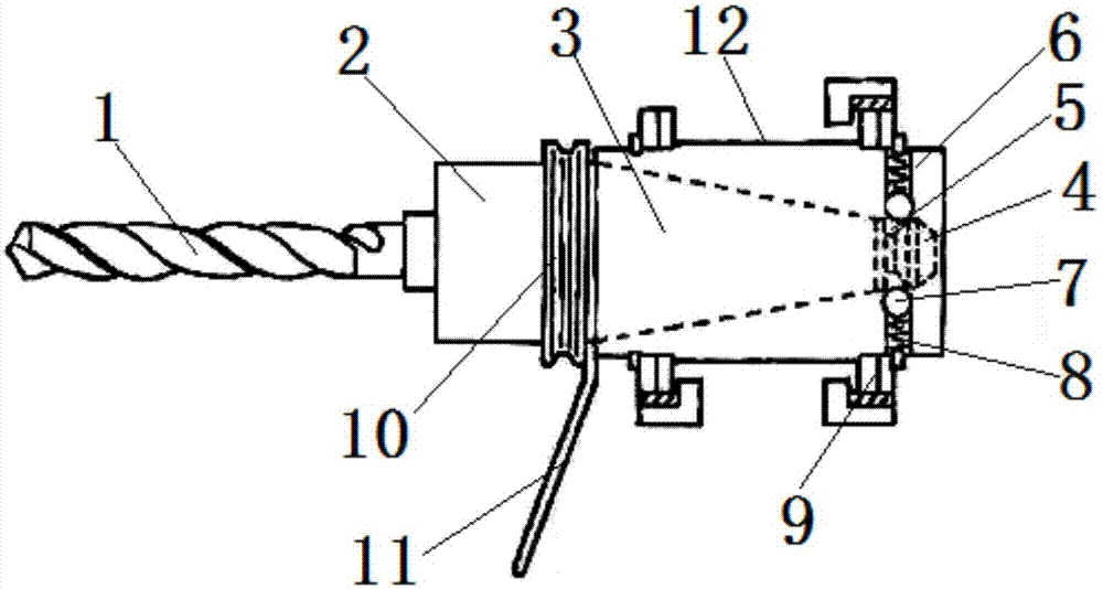
[0013] like figure 1 As shown, a glass mold processing cutter placement device includes a cutter, and the cutter is composed of a cutter head 1, a cutter seat 2 and a connecting piece 3, and the cutter head 1 is installed on one side of the cutter seat 2, and the connection The piece 3 is installed on the other side of the knife seat 2, the connecting piece 3 is tapered, the tail end of the connecting piece 3 is connected with a round head 4, and the round head 4 and the tail end of the connecting piece 3 have a connecting groove 5.

[0014] The connecting piece 3 is covered with a placement cylinder 12, and in order to facilitate fixing the placement cylinder 12, a fixing fast 9 is installed on the placement cylinder 12. On the other side of the opening of the placement cylinder 12, two installation pipes 6 are arranged in the plac...


PUM


Abstract

The invention relates to a glass mold machining cutter placement device which is simple in structure and facilities placement and takeout of a machining cutter. The glass mold machining cutter placement device comprises the cutter formed by a cutter head, a cutter base and a connecting piece, the cutter head is installed on the cutter base, the connecting piece is installed on the cutter base, a round head is connected to the tail end of the connecting piece, and connecting grooves are formed in the round head and the tail end of the connecting piece; the connecting piece is sleeved with a containing barrel, other containing barrels are symmetrically installed at the position, on the other side of an opening of the containing barrel, in the containing barrel, balls and a spring are installed in an installing pipe, and the balls are located at an opening of the installing pipe and are limited in the installing pipe; the spring is located on the inner side of the installing pipe; when the tail end of the connecting piece goes deep into the installing pipe, the balls are embedded into the connecting groove in the tail end of the connecting piece; when the cutter needs to be drawn out, the balls compress the spring, move to the interior of the installing pipe, and break away from the connecting groove, and therefore the cutter is drawn out, size errors caused by friction and the like caused by random placement of the cutter are prevented, and the glass mold machining accuracy is improved.

Description

technical field [0001] The invention relates to a placing device for placing cutters for processing glass molds, and belongs to the technical field of glass mold processing tools. Background technique [0002] The forming mold and initial mold (referred to as Cheng and initial mold) in the glass mold are the key to the production of glass products. Their size determines the capacity of the bottle belly, and the accuracy determines the yield of the bottle. In order to be able to take out the glass bottle from the mold in general, the mold design is made of two semicircular shapes to form a full circle. This is also the characteristic of glass molds that are different from conventional mechanical manufacturing. The process from blank handling, positioning, clamping, and processing is also relatively complicated. Simplifying processing technology, improving product precision, and accelerating the pace of industrial automation are of great significance to the development of gla...

Claims


Application Information

Patent Timeline
Patent Type & Authority Applications(China)
IPC IPC(8): B23Q13/00
CPCB23Q13/00
Inventor 汪兴元张卫江汪卫良
Owner 常熟市兄弟玻璃模具有限公司
Why Eureka
Try Eureka