
System for simultaneously realizing heat dissipation of CPU chip and server

A CPU chip and server technology, applied in the field of data center room environment control, can solve the problems of poor cooling effect, no reduction of equipment, large energy consumption, etc., to achieve the effect of improving energy efficiency ratio, optimizing airflow organization, and improving utilization efficiency

Active Publication Date: 2017-09-19
SICHUAN SUP INFO INFORMATION TECH
View PDF15 Cites 9 Cited by
  • Summary
  • Abstract
  • Description
  • Claims
  • Application Information

AI Technical Summary

Problems solved by technology

[0003] The technical problem to be solved by the present invention is that the existing cooling method consumes a large amount of energy but does not reduce the temperature of the device itself and the chip, and the cooling effect is poor. Its purpose is to provide a system that can simultaneously realize the cooling of the CPU chip and the server. Combining the natural cooling source with the cooling technology of the air-cooled chiller, the server is cooled by a heat pipe radiator close to the heat source. Through the reasonable organization of the airflow, the server and chip-level heat dissipation solution can effectively reduce the PUE on the one hand. Improving energy efficiency utilization, on the other hand, can effectively solve the problems of local hot spots caused by unreasonable airflow organization of precision air conditioners; at the same time, it can effectively improve the space utilization rate of the computer room, and can arrange more cabinets and servers, thereby effectively improving economic benefits and saving land. Effect

Method used


Image

  • System for simultaneously realizing heat dissipation of CPU chip and server
  • System for simultaneously realizing heat dissipation of CPU chip and server

Examples


Embodiment

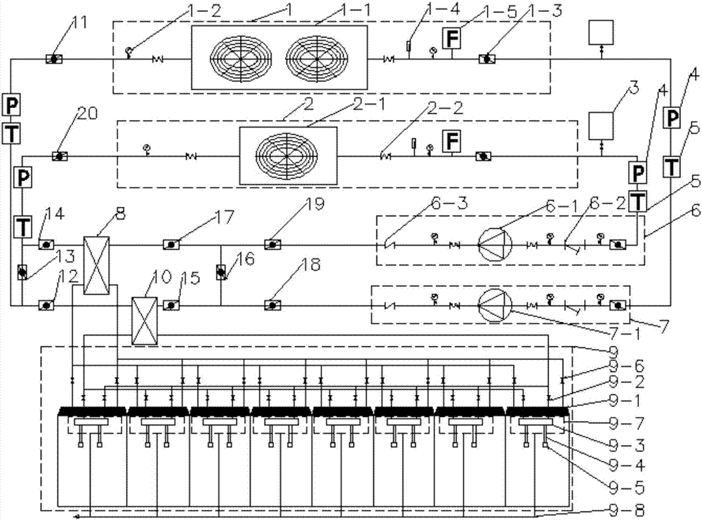
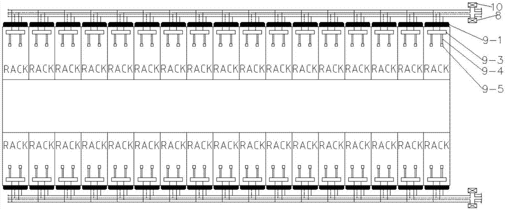
[0035] Such as figure 1 , figure 2 As shown, a system capable of dissipating heat from a CPU chip and a server at the same time includes an outdoor natural cooling unit 1 and an outdoor mechanical refrigeration unit 2, and both the outdoor natural cooling unit 1 and the outdoor mechanical refrigeration unit 2 are sequentially connected to a voltage stabilizing unit 3 , the pump unit and the cold distribution heat exchange unit. The cold distribution heat exchange unit is connected with the corresponding outdoor natural cooling unit 1 and the outdoor mechanical refrigeration unit 2 respectively and forms a circuit respectively. For the convenience of description, it will be connected with the outdoor natural cooling unit 1 The connected pump unit and cooling capacity distribution heat exchange unit are respectively named natural cooling pump unit 7 and chip heat dissipation cooling capacity distribution heat exchanger 10, and the pump unit connected to the outdoor mechanical r...


PUM


Abstract

The present invention discloses a system for simultaneously realizing the heat dissipation of a CPU chip and a server. An outdoor natural cooling unit and an outdoor mechanical refrigerating unit are sequentially connected with a voltage stabilizing unit, a pump set unit and a refrigerating capacity distributing and heat-exchange unit to form a loop respectively. The refrigerating capacity distributing and heat-exchange unit is connected with a CPU chip micro heat pipe radiating unit and a server back plate heat pipe radiating unit. The CPU chip micro heat pipe radiating unit is in contact with the CPU chip in the server. The server back plate heat pipe radiating unit is in contact with a heat dissipating port in the server. The system combines a natural cold source with the air-cooled water chiller unit cooling technology, so that the server is cooled by a heat pipe radiator near a heat source. Based on the reasonable organization of the air flow, the PUE can be effectively reduced and the energy efficiency utilization rate is improved. The problem of local hot spots due to the unreasonable air flow organization of a precise air conditioning unit can be solved. The space utilization rate of a machine room is improved and more cabinets and servers can be arranged in the machine room. Therefore, the economic benefit can be effectively improved and the space-saving effect is better.

Description

technical field [0001] The invention relates to the technical field of environment control in a computer room of a data center, in particular to a system capable of cooling CPU chips and servers at the same time. Background technique [0002] my country's data centers are developing rapidly, with a total of more than 400,000. The annual power consumption exceeds 1.5% of the electricity consumption of the whole society. It is estimated that the energy consumption of data centers will be equivalent to the annual power generation of the Three Gorges Power Station. The PUE is still generally greater than 2.2, which is far behind the international advanced level. The IT equipment of the data center needs to be cooled around the clock. Usually, precision air conditioners are used for cooling in the computer room, so as to ensure the environmental control requirements of the data center. The energy consumption of data center air conditioners accounts for 35%-45% of the total energy...

Claims


Application Information

Patent Timeline
Patent Type & Authority Applications(China)
IPC IPC(8): H05K7/20
CPCH05K7/20718H05K7/20763H05K7/208Y02D10/00
Inventor 朱建斌王丁会严峰王建波
Owner SICHUAN SUP INFO INFORMATION TECH
Learn More