
Three-dimensional micro-fluidic chip and method for improving cell purity magnetic separation

A microfluidic chip and magnetic separation technology, which are applied in the methods of stress-stimulated microbial growth, biochemical equipment and methods, and treatment of microorganisms with electricity/wave energy, etc., can solve the problem of low separation purity, and achieve low prices. , the manufacturing process is simple, and the effect of easy batch generation

Active Publication Date: 2017-09-19
SHANGHAI JIAO TONG UNIV
View PDF4 Cites 4 Cited by
  • Summary
  • Abstract
  • Description
  • Claims
  • Application Information

AI Technical Summary

Problems solved by technology

[0005] Aiming at the problem of low sorting purity of existing cell sorting equipment, the present invention provides a three-dimensional microfluidic chip for high-purity magnetic sorting of cells

Method used


Image

  • Three-dimensional micro-fluidic chip and method for improving cell purity magnetic separation
  • Three-dimensional micro-fluidic chip and method for improving cell purity magnetic separation
  • Three-dimensional micro-fluidic chip and method for improving cell purity magnetic separation

Examples


Embodiment 1

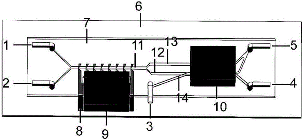
[0073] This embodiment relates to a three-dimensional microfluidic chip for improving the magnetic separation of cell purity, such as figure 1 As shown, the connected inlet unit, horizontal magnetic separation unit, vertical magnetic separation unit and outlet unit.

[0074] The inlet unit includes three inlets, namely cell suspension inlet 1, primary buffer inlet 2 and second buffer inlet 3. The first buffer inlet 2 and the second buffer inlet 3 constitute the first buffer inlet 2 and the second buffer inlet 3 respectively.

[0075] The transverse magnetic separation unit is composed of a transverse magnetic separation microflow channel 11 , a microstructure with a local enhanced magnetic field gradient and a first magnet 9 . The immunomagnetic bead-labeled cell mixture and the buffer solution are respectively injected from the cell suspension inlet 1 and the first buffer inlet 2, and when flowing through the transverse magnetic separation microchannel 11, the magnetic field...

Embodiment 2

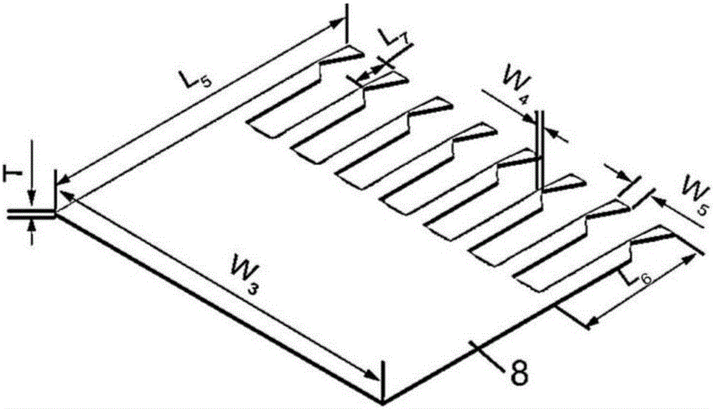
[0096] This embodiment relates to a three-dimensional microfluidic chip for improving the magnetic separation of cell purity, which is a variation example of embodiment 1, the difference is that in embodiment 2, the shape of the inlet of the inlet unit is square, and the sides The length is 1 mm; the shape of the inlet of the outlet unit is square, and the side length is 1 mm; the material of the soft magnetic local magnetic field enhancement structure 8 is iron-nickel alloy, and the shape is a cuboid single-sided comb structure. The soft magnetic local magnetic field enhancement structure has 8 serrations, that is, the magnetic conduction length L6 is 4 mm, the width W5 is 600 μm, and the bottom wall thickness W4 of the groove is 150 μm. The axial free end of the soft magnetic field gradient locally enhanced microstructure and the groove The distance L7 between the bottom ends is 2mm. The first stage magnet 9 and the second stage magnet 10 are square electromagnets, and the s...


PUM

PropertyMeasurementUnit
Diameteraaaaaaaaaa
Lengthaaaaaaaaaa
Heightaaaaaaaaaa

Abstract

The invention provides a three-dimensional micro-fluidic chip for improving cell purity magnetic separation. The three-dimensional micro-fluidic chip comprises an inlet unit, a horizontal magnetic separation unit, a vertical magnetic separation unit and an outlet unit which are sequentially connected, wherein a magnetic attraction direction of the horizontal magnetic separation unit is a horizontal direction; a magnetic attraction direction of the vertical magnetic separation unit is a vertical upward direction. The invention also provides a method for improving the cell purity magnetic separation. The three-dimensional micro-fluidic chip and the method for improving the cell purity magnetic separation provided by the invention provide a concept of firstly enriching and then purifying, have the advantages of high integration, simplicity in operation, high cell separation purity and large flux, and also have the characteristics of high cell recovery rate, large flux, simple manufacturing process, low cost and the like.

Description

technical field [0001] The present invention relates to the fields of cell separation and capture and culture analysis, clinical trials, medical diagnosis, drug efficacy identification, cancer monitoring and treatment effect evaluation, etc., and specifically relates to a three-dimensional microfluidic chip for improving the purity of cells and magnetic separation. method. Background technique [0002] Nowadays, AIDS, cancer and diabetes seriously threaten human health, and they have become the diseases with the highest death rate today. Studies have shown that the study and analysis of specific cells through single-cell analysis has a very important contribution to overcoming major diseases such as AIDS, cancer and diabetes. In order to ensure the precision and accuracy of single-cell analysis and eliminate the influence of heterogeneous cells in single-cell analysis, it is necessary to obtain high-purity target cells. In the field of cell separation, as far as the curren...

Claims


Application Information

Patent Timeline
IPC IPC(8): C12M1/00C12M1/42C12N5/00C12N13/00
CPCC12M23/16C12M35/06C12M47/04C12N5/00C12N13/00
Inventor 陈迪林树靖仇三铭沈亦欢郅晓崔大祥
Owner SHANGHAI JIAO TONG UNIV
Learn More