motor power unit

A power plant and motor type technology, applied in power plant, electric power plant, electromechanical device and other directions, can solve the problems of easy oil immersion, large-scale, complicated casing, etc.

Active Publication Date: 2019-09-17
HONDA MOTOR CO LTD
View PDF6 Cites 0 Cited by
  • Summary
  • Abstract
  • Description
  • Claims
  • Application Information

AI Technical Summary

Problems solved by technology

[0005] In addition, in the above-mentioned conventional device, since the upper part of the transmission storage chamber directly constitutes the first breather chamber, the oil carried by the gears stored in the transmission storage chamber is easy to infiltrate into the first breather chamber, and the oil in the first breather chamber Difficult to separate oil mist sufficiently
For this reason, it is necessary to further form a second vent chamber above the first vent chamber to separate the oil mist, and there is a problem that the structure is complicated and the casing is enlarged due to the installation of two vent chambers.

Method used


Image

  • motor power unit
  • motor power unit
  • motor power unit

Examples


Embodiment Construction

[0025] Below, according to Figure 1 to Figure 5 Embodiments of the present invention will be described.

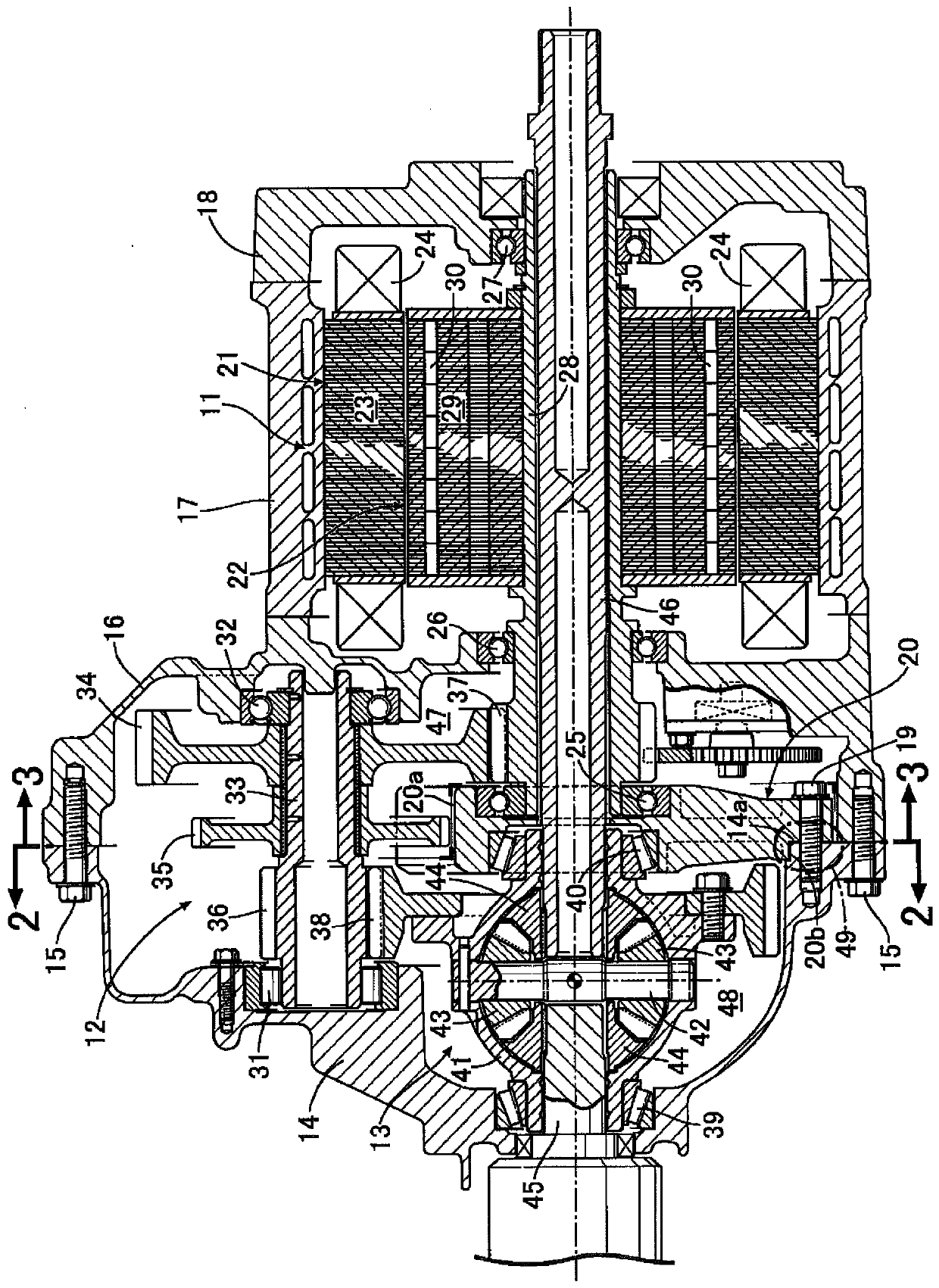
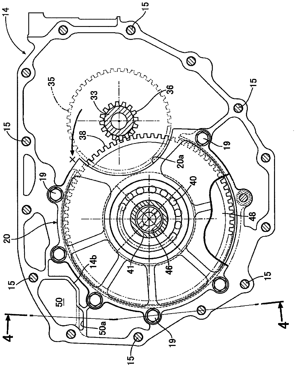
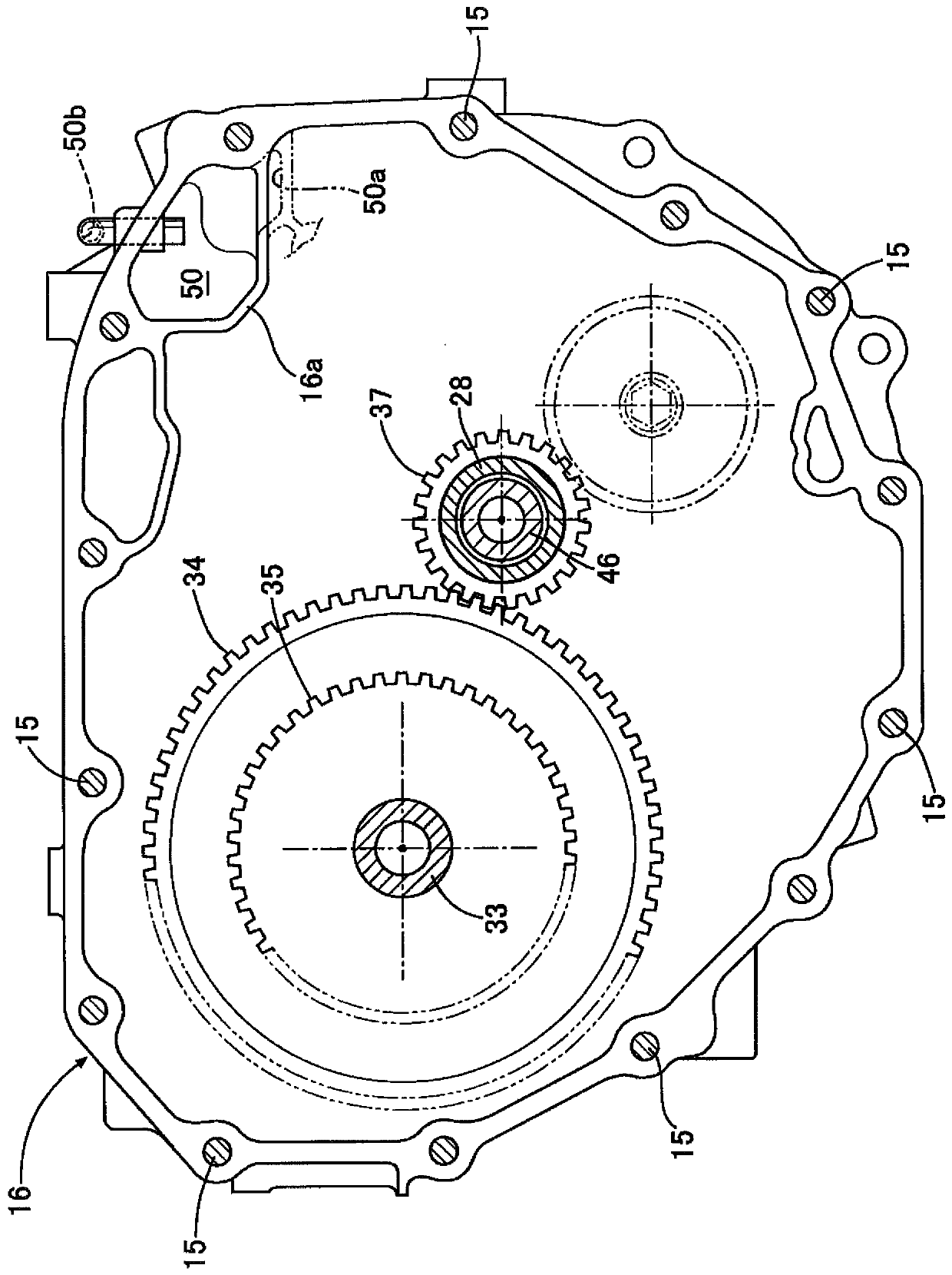
[0026] Such as figure 1 As shown, the motor-type power unit used as the power unit of the electric vehicle integrally has an electric motor 11, a speed reducer 12 and a differential 13, and the outer contour of the motor-type power unit is composed of the following parts: The transmission case 14; the motor / transmission case 16 connected to the right end of the transmission case 14 by bolts 15; the motor center case 17 connected to the right end of the motor / transmission case 16 by unillustrated bolts; The motor side case 18 at the right end of the motor center case 17; the middle case 20 bonded to the inner surface of the transmission case 14 with bolts 19 . . .

[0027] The electric motor 11 is housed inside the motor center case 17 and the motor side case 18 . In addition, the intermediate case 20 partitions the inside of the transmission case 14 and the motor / trans...


PUM


Abstract

The invention provides a motor-driven power unit to prevent oil from entering a breather chamber arranged in a casing of the motor-driven power unit with a simple structure. The motor-driven power unit comprises a first case (17, 18) for housing an electric motor (11), second cases (14, 16) for accommodating a speed reducer (12) and a differential (13), a third case (20) that separates a speed reducer storage chamber (47) and a differential storage chamber (48), and a breather chamber (50) that is arranged above the second cases (14, 16). An opening (50a) communicating with the internal space of the speed reducer storage chamber (47) and a communicating hole (50b) communicating with the atmosphere are formed in the breather chamber (50), and a final driving gear (38), which transmits a driving force to a final driven gear (38) of the differential (13), of the speed reducer (12) is located at the opposite side of the opening (50a) across the differential storage chamber (48).

Description

technical field [0001] The present invention relates to a motor-type power plant that transmits rotation of a rotor shaft of an electric motor to a differential through a speed reducer, and one of a pair of output shafts of the differential is arranged inside the rotor shaft. Background technique [0002] In this motor type power unit, the following device is known from the following patent document 1: a device that accommodates the main gear, the pinion gear, the final driving gear, the final driven gear, etc. that transmit the driving force of the electric motor to the differential. A first breather chamber and a second breather chamber are formed on the upper part of the transmission housing chamber, and the oil mist mixed in the breathing gas is separated by the first and second breather chambers to prevent diffusion into the atmosphere. [0003] prior art literature [0004] Patent Document 1: Japanese Patent No. 5237424 [0005] In addition, in the above-mentioned co...

Claims


Application Information

Patent Timeline
Patent Type & Authority Patents(China)
IPC IPC(8): B60K1/00B60K17/16H02K7/116H02K5/04
CPCB60K1/00B60K17/16H02K5/04H02K7/116
Inventor 久保田和高岛太郎喜友名美晴
Owner HONDA MOTOR CO LTD
Why Eureka
Try Eureka