Underwater motor

A motor and main body technology, applied in electromechanical devices, coupling devices, electrical components, etc., can solve problems such as damaged cables, poor wiring workability, and poor workability

Inactive Publication Date: 2006-08-16
EBARA CORP
View PDF0 Cites 0 Cited by
  • Summary
  • Abstract
  • Description
  • Claims
  • Application Information

AI Technical Summary

Problems solved by technology

[0011] (3) When installing the underwater motor, since the cables 1 and 1a are connected, rough work may damage the cables
[0012] (4) When performing regular maintenance of the underwater motor pump on site, remove the connection between the power cable 1 and the power control panel, such as Figure 11 As shown, the pump body must be transported to the maintenance site with a long and thick cable, so the workability is poor.
Therefore, when the cable 1 is thick, the wiring workability is poor

Method used


Image

  • Underwater motor
  • Underwater motor
  • Underwater motor

Examples


Embodiment Construction

[0036] specific implementation

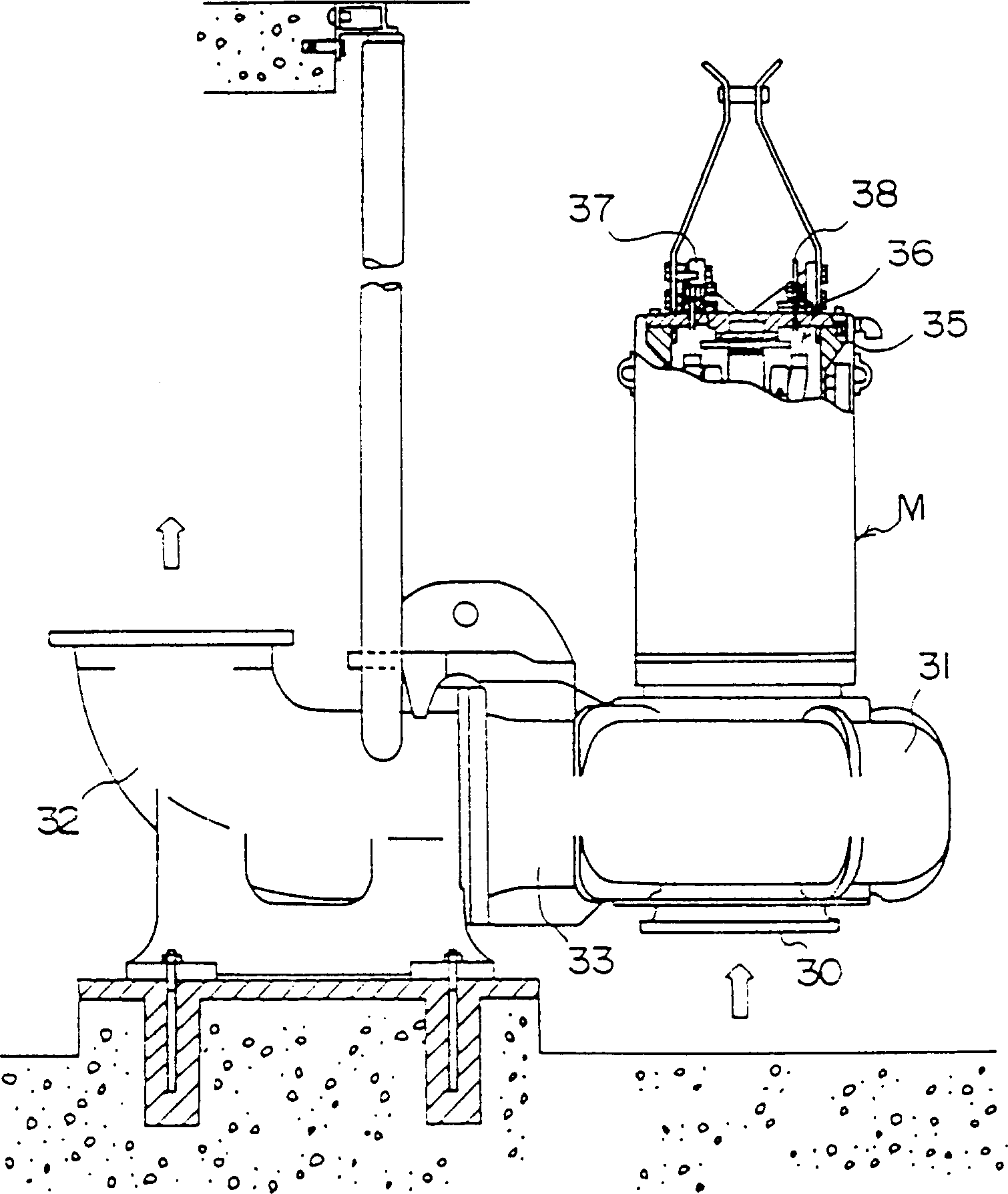
[0037] figure 1 A vertical shaft type submersible pump using the submersible motor of the present invention is shown. An impeller is provided in a pump casing 33 having a suction port 30 , a scroll chamber 31 , and a discharge pipe 32 , and an underwater motor M is assembled above the pump casing 33 . The structure of the underwater motor M is that the motor body 36 is incorporated into the cylindrical motor box 35 , and the structure of its connector is: a power cable 37 and a control cable 38 are detachably connected on the top of the motor box 35 .

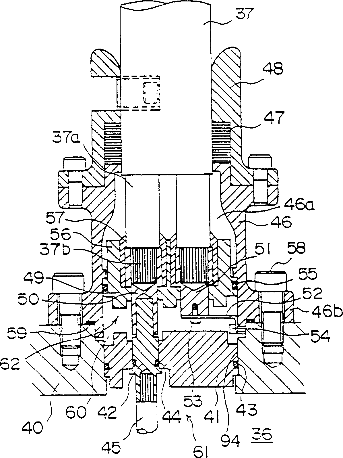
[0038] Such as figure 2 or image 3 As shown, on the motor body 36 side, a cover plate 41 made of an insulator is attached to the opening of the top plate 40 of the box 35, and a male side connector 42 protruding outward is provided on the cover plate 41. The top corner of the joint 42 is chamfered into a rounded guide face 42a. Between the top plate 40 and the cover plate 41 , and betwee...


PUM


Abstract

The invention provides an underwater motor which facilitates works, and further more into which water hardly infiltrates. An underwater motor has a motor main body, a cable through which a power is supplied to the motor main body or electrical signals are transmitted / received to / from the motor main body, and connectors which are provided on both the motor main body and the cable on order to connect them detachably to each other. The connectors have covering members whose openings are coupled with each other detachably and liquid-tightly, insulating members which cover the openings of the covering members and contact members, which are attached to the insulating members and which are coupled with each other in accordance with the coupling of the covering members for electrical connection. At least one of the contact members is attached, so as to be allowed to make minute movements in a direction crossing the coupling direction with respect to the covering members.

Description

technical field [0001] The present invention relates to a dry underwater motor, in particular to an underwater motor connected by a connector for cables and a waterproof connector for the motor. Background technique [0002] In underwater motors, a highly reliable waterproof structure is required for the lead-in part where power and control cables are led into the motor. The structure of this part in the prior art has the following: [0003] (1) A structure in which the end of the cable is fixed and sealed with a rubber gasket or resin. [0004] (2) A cable end portion is molded with an elastic body such as rubber, and the portion is fixed and sealed. [0005] Figure 10 An example of the above (1) is shown, and the structure of the cable connection part is shown in detail. The procedure for connecting a power source and the like to the motor with this configuration will be described below. [0006] First connect the core wire part 2 of the power cable 1 with the core wi...

Claims


Application Information

Patent Timeline
IPC IPC(8): H02G15/08H01R13/52H01R13/523H02G15/02H02K5/132H02K5/22
Inventor 山田良之
Owner EBARA CORP
Why Eureka
Try Eureka