Sliding window

A sliding window and window frame technology, applied in the field of windows, can solve the problems of incomplete sealing, poor waterproof performance of sliding windows, penetration into the wall, etc., and achieve the effect of easy installation and disassembly, convenient and flexible installation and disassembly, and good waterproof performance

Inactive Publication Date: 2011-06-01
宝业集团浙江建设产业研究院有限公司
View PDF1 Cites 0 Cited by
  • Summary
  • Abstract
  • Description
  • Claims
  • Application Information

AI Technical Summary

Problems solved by technology

[0004] The main defect of existing sliding windows is poor waterproof performance
The joint between the window frame and the wall is often treated with sealant. The sealant will age with the increase of use time or the seal will be incomplete due to construction reasons, resulting in a decrease in sealing performance, and outdoor rainwater will easily seep into the wall; window frame The outer frame slide rails, inner frame slide rails, and baffles of the lower horizontal frame form a groove structure, which is easy to accumulate water, and the accumulated water is easy to seep into the wall from the connection between the lower horizontal frame and the mullion; the outer frame of the window frame and The inner frame is connected by heat insulation strips. With the increase of use time, due to the deformation of the window frame or the aging of the heat insulation strips, the sealing performance between the heat insulation strips and the inner and outer frames will decrease, and the accumulated water will seep into the wall from the joints.
[0005] In view of this, the present invention improves on the basis of the existing broken bridge heat-insulating aluminum alloy sliding window, and provides a new type of sliding window to overcome the disadvantage of poor waterproof performance of the traditional sliding window

Method used


Image

  • Sliding window
  • Sliding window
  • Sliding window

Examples


Embodiment Construction

[0021] The specific embodiments of the present invention will be described below in conjunction with the accompanying drawings.

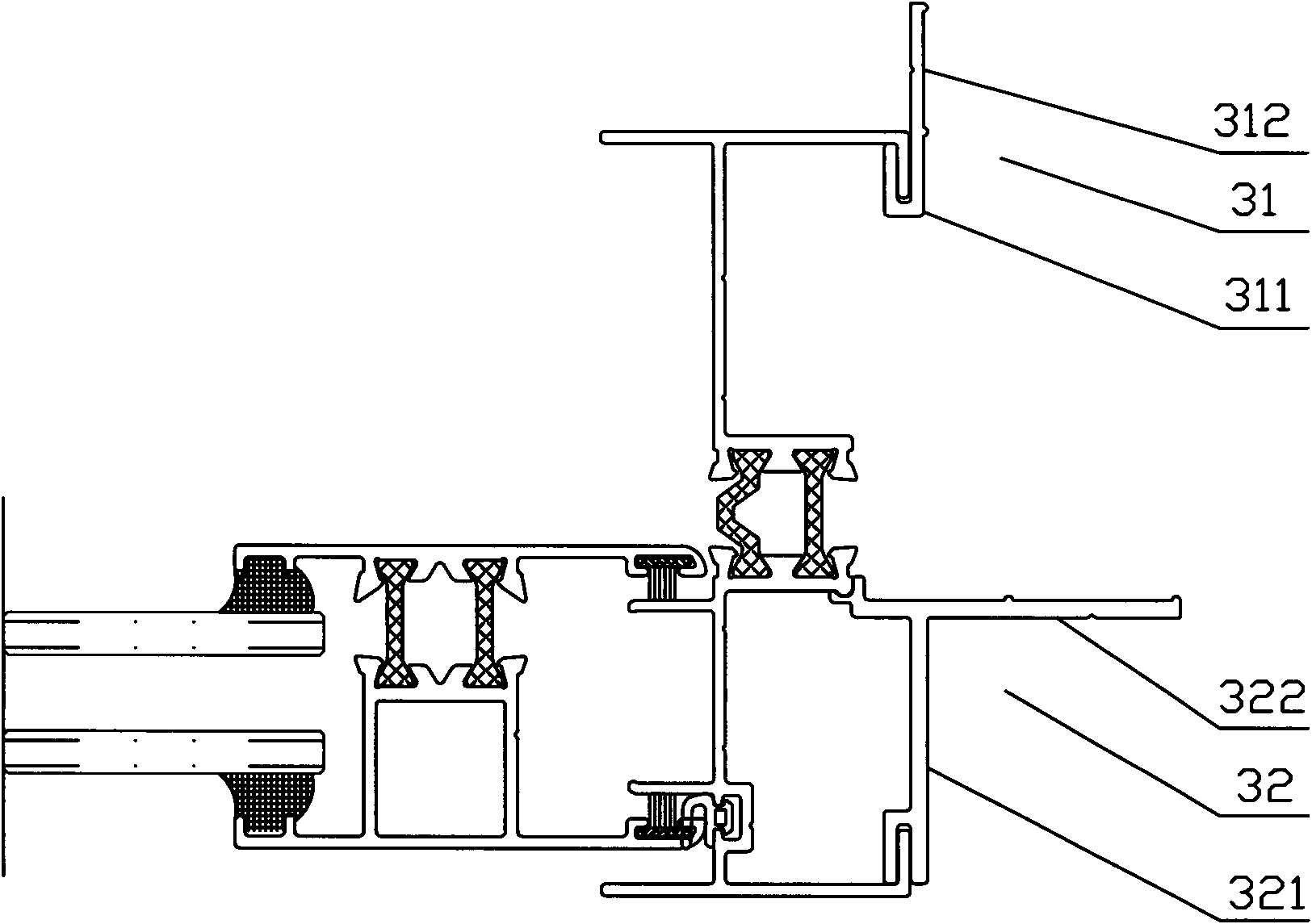
[0022] Such as image 3 As shown, the present invention provides that the mullion of the sliding window frame is provided with installation strips, including an inner installation strip 31 and a vertical outer installation strip 32, wherein the inner installation strip 31 includes an engaging part 311 and an installing part 312, and the engaging part 311 A groove is set, and the inner frame of the window frame is located at the edge part of the indoor side to coincide with the groove, and the inner installation strip can be engaged with the inner frame through the card groove; the outer installation strip 32 includes an engaging part 321 and an installation part 322, The joint part 321 is provided with two grooves, and the two edge parts of the outer frame of the window frame coincide with the two grooves respectively, and the outer installation str...


PUM


Abstract

The invention provides a sliding window. A window frame of the sliding window is provided with installation strips, each installation strip comprises a clamping part, the clamping part of the installation strip and an outer frame or an inner frame of the window frame are respectively provided with a complementary clamping structure, and the installation strip is installed at the window frame by the clamping structure; the installation strips are divided into inner installation strips and outer installation strips according to positions, and the outer installation strips are divided into upright outer installation strips, upper outer installation strips and lower outer installation strips according to positions; and except for the clamping part, the inner installation strips and the outer installation strips also comprise installation parts, the window frame is installed on a wall body by the installation parts, and the installation parts of the inner installation strip and the outer installation strip are mutually vertical. The sliding window provided by the invention has the advantages of convenient installation and disassembly and good waterproof performance.

Description

technical field [0001] The invention relates to a window, in particular to a metal frame sliding window. Background technique [0002] Currently commonly used aluminum alloy windows have the characteristics of exquisite appearance, no rust, long service life, and good sealing performance, and are generally loved by users. However, this type of product has poor thermal insulation because the window frame is made of metal material and has strong thermal conductivity. In order to enhance the thermal insulation of aluminum alloy window frames, people have improved the hollow aluminum alloy window frames and designed high-quality broken bridge thermal insulation windows. In the patent, the inventor divides the window frame into an outer frame and an inner frame by using a thermal insulation column to prevent heat transfer between the outer frame and the inner frame. At present, the cross-section of the lower horizontal frame of the common broken bridge heat insulation sliding w...

Claims


Application Information

Patent Timeline
Patent Type & Authority Patents(China)
IPC IPC(8): E06B3/46E06B3/26E06B7/14E06B7/22E05D13/00
Inventor 余亚超陈力徐松南李智文
Owner 宝业集团浙江建设产业研究院有限公司
Why Eureka
Try Eureka