
Rotary clamping type shin support and shin pad assembled structure for total knee replacement and implementation method thereof

A technology of total knee replacement and assembly structure, applied in the direction of skull, knee joint, bone implants, etc., can solve the problem of unsuitable tibial tray and tibial spacer, and achieve the effect of improving life expectancy and shortening the learning curve

Active Publication Date: 2017-09-19
SOUTH CHINA UNIV OF TECH
View PDF11 Cites 1 Cited by
  • Summary
  • Abstract
  • Description
  • Claims
  • Application Information

AI Technical Summary

Problems solved by technology

[0005] The main purpose of the present invention is to overcome the problem that the tibial support and tibial spacer in the prior art are not suitable for individualized patients’ total knee joint surgery, and to provide a rotary clamping total knee replacement tibial support with good stability and easy manufacture Assembly structure and realization method with tibial spacer

Method used


Image

  • Rotary clamping type shin support and shin pad assembled structure for total knee replacement and implementation method thereof
  • Rotary clamping type shin support and shin pad assembled structure for total knee replacement and implementation method thereof
  • Rotary clamping type shin support and shin pad assembled structure for total knee replacement and implementation method thereof

Examples


Embodiment

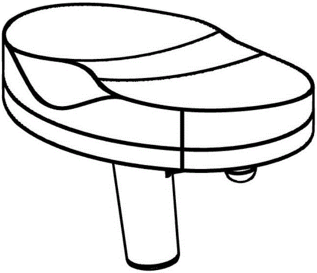
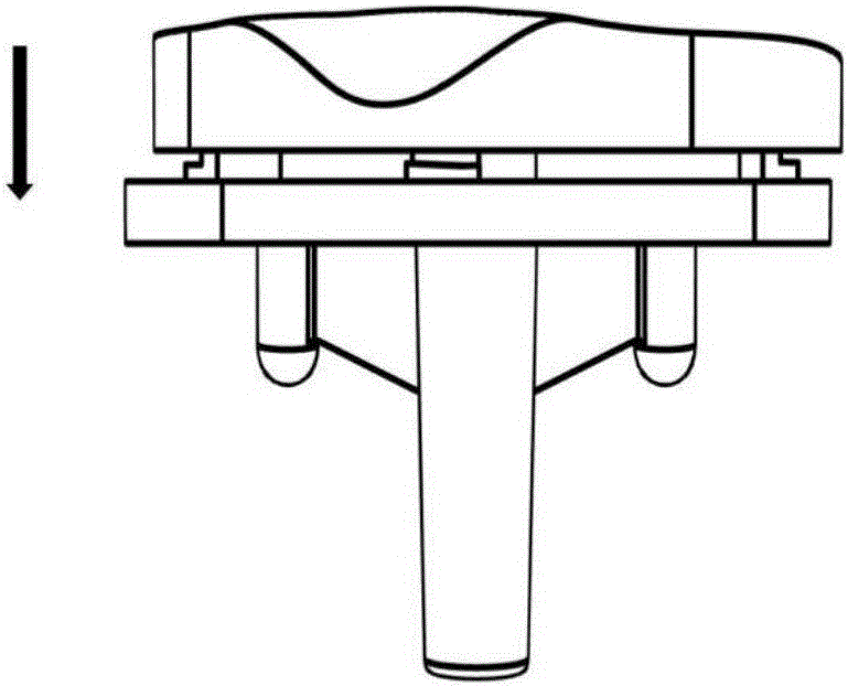
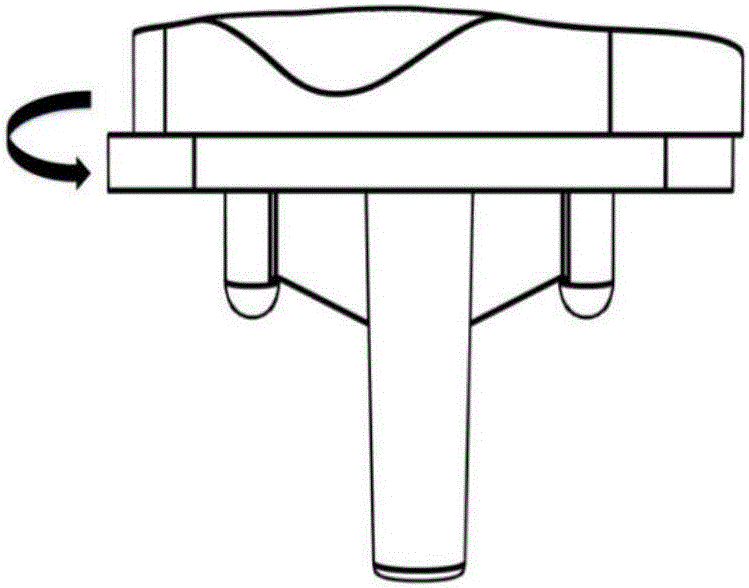
[0047] like figure 1 , Figure 3(a)-Figure 3(c) and Figure 4(a)-Figure 4(c) As shown, the assembly structure of the rotating clamping type total knee replacement tibial support and tibial spacer in this embodiment has:

[0048] 1) There is a fixed cylinder 1 on the lower surface of the tibial spacer (that is, the contact surface with the tibial tray);

[0049] 2) On the lower surface of the tibial spacer (that is, the contact surface with the tibial tray), there are three arc bodies 2 with a locking mechanism, and the three arc bodies 2 are respectively located in the front of the tibial spacer and in the left and right directions;

[0050] 3), there is a fixed circular groove 3 on the upper surface of the tibial support (that is, the contact surface with the tibial spacer);

[0051] 4) On the upper surface of the tibial support (that is, the contact surface with the tibial spacer), there are three circular arc grooves 4 with a locking mechanism, and the three circular arc...


PUM


Abstract

The invention discloses a rotary clamping type shin support and shin pad assembled structure for total knee replacement and an implementation method thereof. The assembled structure comprises a fixed circular groove and a plurality of circular arc grooves with locking mechanisms, wherein the fixed circular groove and the circular arc grooves are arranged at the upper surface of the shin support, the fixed circular groove is arranged in the center position of the upper surface of the shin support, and a positioning bone column is arranged at the lower surface of the shin support; a fixed round column and a plurality of circular arc bodies matched with the circular arc grooves are arranged at the lower surface of the shin pad; when assembled, the fixed round column on the shin pad is aligned with the fixed circular groove of the shin support and pressed in downward, so the shin support is totally fit to the shin pad, then the shin pad is rotated so that the circular arc bodies rotate in the circular arc grooves, the boundaries are completely superposed, the locking mechanisms on the circular arc grooves and the circular arc bodies take effect, and the shin pad and the shin support are completely fixed. The rotary clamping type shin support and shin pad assembled structure for total knee replacement can ensure the assembling stability of the shin support and the shin pad and improve the quality of a total knee replacement operation, and a shin support and shin pad device for total knee replacement can be quickly produced for individual patients.

Description

technical field [0001] The invention relates to a tibial support and a tibial spacer for surgery, and more specifically, to an assembly structure and a realization method of a personalized rotary clamping type total knee replacement tibial support and a tibial spacer. Background technique [0002] Total knee replacement surgery is developing rapidly all over the world every year, and has become the most effective method for the treatment of advanced osteoarthritis, rheumatoid arthritis and other diseases. However, complications such as prosthetic loosening, flexion and deformity after weight-bearing, and pain after surgery have also attracted the attention of orthopedic surgeons. [0003] Moreover, due to individual differences, the coverage of mass-produced tibial trays and osteotomy sections is insufficient, and the assembly of tibial spacers and tibial trays is not good, which will affect the quality of surgery. [0004] Thanks to the rapid development of computer and di...

Claims


Application Information

Patent Timeline
IPC IPC(8): A61F2/28A61F2/38A61F2/30
CPCA61F2/28A61F2/30942A61F2/389A61F2002/2892A61F2002/30948Y02P10/25
Inventor 宋长辉周游杨永强王安民
Owner SOUTH CHINA UNIV OF TECH
Learn More