Automatic adjuster

A regulator and automatic technology, applied in the direction of engine components, brake actuators, functional valve types, etc., can solve the problems of difficult control of gas flow, increased cost of one-way valves, complex structure of brake valves, etc., to achieve good gas flow , easy processing, simple structure

Pending Publication Date: 2017-09-15
谢洪川
View PDF0 Cites 0 Cited by
  • Summary
  • Abstract
  • Description
  • Claims
  • Application Information

AI Technical Summary

Problems solved by technology

[0002] The brake valve belongs to a part of the automobile air brake braking system. An automatic switch valve is often used in the brake valve. In a working pressure adjustable automatic switch brake valve and its realization method, the function of the automatic regulator is to connect the Air port and air outlet, but in the air return process of the brake valve, it is necessary to add an additional one-way valve to realize the air return process. After the additional one-way valve is added, the disadvantages of the brake valve are very prominent: 1 1. Additional one-way valves increase costs; 2. Some air passages need to be set separately, and one-way valves are installed in the air passages, which makes the structure of the entire brake valve complicated and is not conducive to processing and production; 3. Too many and chaotic airways can make the flow of gas more difficult to control

Method used


Image

  • Automatic adjuster
  • Automatic adjuster
  • Automatic adjuster

Examples


Embodiment

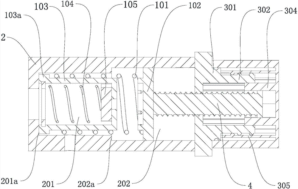
[0034] Such as Figure 1-5 As shown, an automatic regulator includes a valve body 2 and a valve core. The valve core is located in the valve body and can move axially along the valve body. One end of the valve body is provided with an inlet and the valve wall is provided with an outlet; the valve core includes Pressure regulating spring 101, regulating spool 103, return spring 104, spool block 105; the pressure regulating spring is arranged along the axial direction of the valve body, and the pressure regulating spring is sleeved on the regulating spool and in the initial state, one end is connected to the valve body The bottom is movably connected. The top of the regulating valve core is provided with an opening communicating with the opening of the valve body and extends inward from the opening to the bottom of the regulating valve core to form a cavity. The bottom of the cavity is provided with a through hole, and one end of the return spring It is connected with one end of...


PUM


Abstract

The invention discloses an automatic adjuster. The automatic adjuster comprises a valve body and a valve element; the valve element is arranged in the valve body and can move in the axial direction of the valve body, one end of the valve body is provided with an inlet, and the valve wall is provided with an outlet; the valve element comprises a pressure-adjustment spring, an adjustment valve element body, a reset spring and a valve element block; the pressure adjustment spring is arranged in the axial direction of the valve body and is connected to the adjustment valve element body in a sleeved manner, and one end of the pressure adjustment spring is movably connected with the bottom of the valve body in the initial state; the top of the adjustment valve element body is provided with an opening communicating with a valve body opening and stretches inwards from the opening to the bottom of the adjustment valve element body to from a cavity, and the bottom of the cavity is provided with a through hole; and one end of the reset spring is connected with one end of the valve element block, the valve element block is embedded into the cavity of the adjustment valve element body, the other end of the reset spring is fixed to the top of the adjustment valve element body, and the top edge of the adjustment valve element body is furthermore provided with an annular adjustment chuck. By means of the automatic adjuster, two-way ventilation can be achieved, the work pressure is adjustable, self-locking can also be achieved, and error operation is avoided.

Description

technical field [0001] The present invention relates to a valve, in particular to an automatic regulator. Background technique [0002] The brake valve is a part of the automobile air brake braking system. An automatic switch valve is often used in the brake valve. In an automatic switch brake valve with adjustable working pressure and its realization method, the function of the automatic regulator is to communicate with the The air port and air outlet, but in the air return process of the brake valve, it is necessary to add an additional one-way valve to realize the air return process. After the additional one-way valve is added, the disadvantages of the brake valve are very prominent: 1 1. Additional one-way valves increase costs; 2. Some air passages need to be set separately, and one-way valves are installed in the air passages, which makes the structure of the entire brake valve complicated and is not conducive to processing and production; 3. Too many and chaotic Open...

Claims


Application Information

Patent Timeline
IPC IPC(8): F16K17/06F16D65/16F16D121/02F16D125/02
CPCF16D65/16F16K17/06F16D2121/02F16D2125/02
Inventor 谢洪川
Owner 谢洪川
Why Eureka
Try Eureka