
Moving bed anaerobic fermentation reactor

An anaerobic fermentation and active bed technology, applied in the direction of gas production bioreactors, biochemical instruments, biochemical equipment and methods, etc., can solve problems such as pH value, difficult temperature control, difficult heat and mass transfer, and large water consumption , to achieve the effect of saving sewage treatment costs, simplifying the treatment process, and occupying less equipment

Pending Publication Date: 2017-09-12
李江平
View PDF0 Cites 4 Cited by
  • Summary
  • Abstract
  • Description
  • Claims
  • Application Information

AI Technical Summary

Problems solved by technology

Its disadvantages are: (1) large water consumption, high energy consumption in winter (up to 30-45% of self-production capacity); (2) large amount of sewage, and secondary pollution of biogas slurry that cannot be used up, requiring high investment Sewage treatment costs; (3) A large amount of agricultural and forestry solid waste such as straw cannot be treated
The disadvantages are: (1) Because there is no or almost no free water flow between the materials in the dry fermentation reactor, there is a serious concentration gradient in the fermentation material, and heat and mass transfer are difficult; PH value, temperature and other parameters are difficult to control, and the equipment technical requirements are very high; (3) For rigid reactors, the remaining biogas must be replaced at the end of gas production to ensure safe operation; (4) Large and medium-sized fermentation reactors enter and exit Material difficulty
A large amount of agricultural and forestry waste such as straw and other solid biological organic matter have not been effectively utilized

Method used


Image

  • Moving bed anaerobic fermentation reactor

Examples


Embodiment Construction

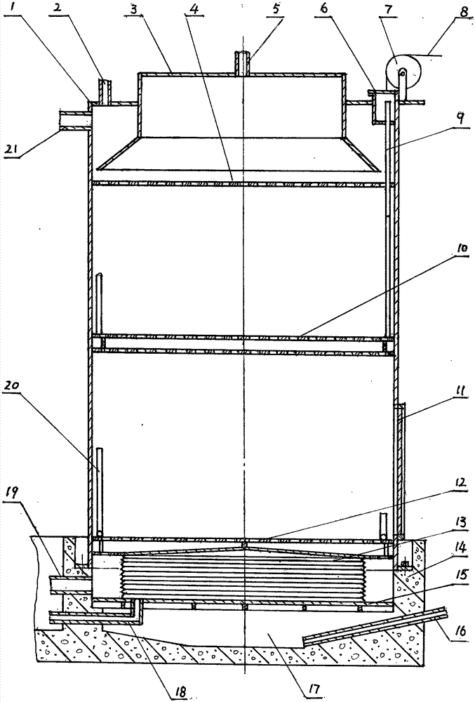
[0017] The accompanying drawing shows that the tank body 1 is a vertical device, the upper part is provided with a gas collecting hood 3, and the lower part of the gas collecting hood is in the tank body 1. The top of the gas collecting hood is provided with a biogas outlet pipe 5 communicating with it, and the outlet pipe communicates with a biogas storage tank (not shown in the figure). The baffle plate 4 is arranged under the gas collecting hood 3, and its periphery is fixed on the inner wall of the tank body 1. The baffle is a perforated plate. The bottom of baffle plate 4 is provided with upper movable bed 10, and above upper movable bed is provided with 4 telescopic suspension rods 9, and the suspension rod top is connected with the wire rope 8 on the pulley 7 that is fixed on tank body 1 top. Wire rope is connected with winch (not shown in the figure). When the upper movable bed 10 rises to a predetermined position, it can be fixed. Suspender rod 9 tops and wire rope...


PUM


Abstract

A moving bed anaerobic fermentation reactor can be used for producing biogas. The reactor includes a tank body, a gas collecting hood, a water outlet tube and a water inlet tube. The gas collecting hood is arranged at the upper part of the tank body, a porous baffle plate is arranged under the gas collecting hood, an upper moving bed and a lower moving bed are arranged below the baffle plate, and the upper moving bed is provided with a lifting device. An airbag is arranged below the lower moving bed, and a side door is arranged at the lower part of the tank body. When the reactor works, the tank body is filled with straws and other fermentation materials from the side door through a loader to make a space between the baffle plate and the lower moving bed full; a biogas slurry is injected to submerge the lower opening of the gas collecting hood, and anaerobic fermentation is carried out;; the volume of the fermentation materials continuously decrease with the discharge of biogas, and the airbag is timely inflated and expands to keep the liquid level unreduced; and liquid discharge and residue discharge are sequentially carried out after the biogas production is finished. The reactor has the advantages of less water, direct reuse of sewage, zero emission, high efficiency and convenience in material feeding and discharging, and less device investment.

Description

technical field [0001] The invention relates to an anaerobic fermentation reactor used in biogas production. Background technique [0002] Biogas is a clean and renewable energy source. Anaerobic fermentation reactor is the core device in biogas production. Anaerobic fermentation reactors (hereinafter referred to as fermentation reactors) are generally divided into two categories, namely wet fermentation reactors and dry fermentation reactors. The several reactors disclosed in pages 49-57 of "Design and Application of Large and Medium-Sized Biogas Projects" published by Chemical Industry Press in 2013 and edited by Tang Yanfang are all wet fermentation reactors, and their basic structures include tanks, outlet pipes , Inlet pipe. During work, the fermented material is mixed with water and sent into the tank for anaerobic fermentation to generate biogas. Due to the limitations of pipeline valves and water pumps, the particle size of the material in the mixed solution cann...

Claims


Application Information

Patent Timeline
Patent Type & Authority Applications(China)
IPC IPC(8): C12M1/107C02F11/04
CPCC12M21/04C12M23/36C12M23/52C12M29/04C12M37/04
Inventor 李江平
Owner 李江平
Learn More