
Energy storage type air source heat pump system

An air source heat pump and energy storage technology, applied in the field of heat pumps, can solve the problems of restricting the operation and promotion of air source heat pumps, high operation energy consumption, poor applicability, etc. Effect

Active Publication Date: 2017-09-05
BEIJING UNIVERSITY OF CIVIL ENGINEERING AND ARCHITECTURE
View PDF0 Cites 0 Cited by
  • Summary
  • Abstract
  • Description
  • Claims
  • Application Information

AI Technical Summary

Problems solved by technology

However, the characteristics and operation practices of air source heat pumps also show that: (1) the energy efficiency of air source heat pumps in winter is high when the outdoor air temperature is high during the day, and the energy efficiency is low when the outdoor air temperature is low at night; The energy efficiency is low when the temperature is high, and the energy efficiency is high when the outdoor air temperature is low at night, which is just opposite to the energy load of the building. The heating performance of the air source heat pump is contrary to the change of the building load with the outdoor temperature.
(2) Susceptible to the problem of defrost, especially for areas with hot summer and cold winter
The above problems lead to high energy consumption, poor applicability and uneconomical operation, which are important factors restricting the operation and promotion of air source heat pumps

Method used


Image

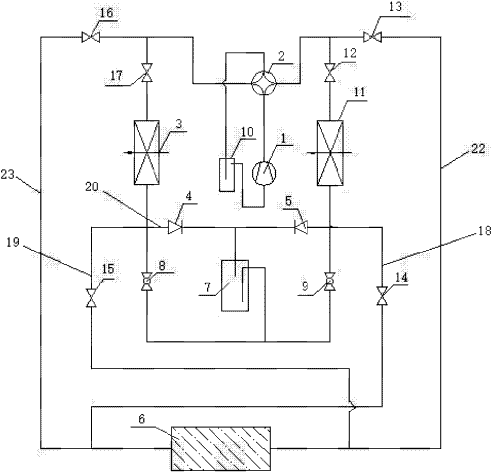
  • Energy storage type air source heat pump system

Examples


Embodiment Construction

[0030] Embodiments of the present invention will be further described in detail below in conjunction with the accompanying drawings and examples. The following examples are used to illustrate the present invention, but should not be used to limit the scope of the present invention.

[0031] In the description of the present invention, the terms "first", "second", "third", etc. are used for descriptive purposes only, and should not be understood as indicating or implying relative importance. It should be noted that, unless otherwise clearly stipulated and limited, the terms "installation", "connection" and "connection" should be understood in a broad sense, for example, it can be a fixed connection, a detachable connection, or an integral connection; It can be mechanically connected or electrically connected; it can be directly connected or indirectly connected through an intermediary. Those of ordinary skill in the art can understand the specific meanings of the above terms i...


PUM


Abstract

The invention belongs to the technical field of heat pumps, and particularly relates to an energy storage type air source heat pump system. The system comprises a compressor, an indoor heat exchanger, a first throttling mechanism, an outdoor heat exchanger, a reversing valve and a phase change accumulator. A first regulating valve is arranged on a pipeline between the reversing valve and the outdoor heat exchanger. A second regulating valve is arranged on a pipeline between the reversing valve and the indoor heat exchanger. A first end of the phase change accumulator communicates with a pipeline between the first regulating valve and the reversing valve through a first pipeline. A second end of phase change accumulator communicates with a pipeline between the second regulating valve and the reversing valve through a second pipeline. The first pipeline and the second pipeline are provided with a third regulating valve and a fourth regulating valve correspondingly. A pipeline between the first throttling mechanism and the outdoor heat exchanger communicates with a pipeline between the fourth regulating valve and the second end of the phase change accumulator through a third pipeline. A pipeline between the first throttling mechanism and the indoor heat exchanger communicates with a pipeline between the third regulating valve and the first end of the phase change accumulator through a fourth pipeline. The energy storage type air source heat pump system improves energy efficiency and has an important meaning for energy conservation.

Description

technical field [0001] The invention belongs to the technical field of heat pumps, in particular to an energy storage type air source heat pump system. Background technique [0002] The air source heat pump has the advantages of using inexhaustible air as a low-level heat source, wide application range, and high equipment utilization rate. However, the characteristics and operation practices of air source heat pumps also show that: (1) the energy efficiency of air source heat pumps in winter is high when the outdoor air temperature is high during the day, and the energy efficiency is low when the outdoor air temperature is low at night; The energy efficiency is low when the temperature is high, and the energy efficiency is high when the outdoor air temperature is low at night, which is just opposite to the energy load of the building. The heating performance of the air source heat pump is contrary to the change of the building load with the outdoor temperature. (2) Suscepti...

Claims


Application Information

Patent Timeline
IPC IPC(8): F25B13/00F25B29/00F25B41/04F25B41/06F25B41/20F25B41/31
CPCF25B13/00F25B29/003F25B2400/24F25B2313/02741F25B41/30F25B41/20Y02E60/14
Inventor 胡文举贾鹏徐荣吉高岩史永征
Owner BEIJING UNIVERSITY OF CIVIL ENGINEERING AND ARCHITECTURE
Learn More