Eureka AIR delivers breakthrough ideas for toughest innovation challenges, trusted by R&D personnel around the world.

Driving shaft bell-shaped housing structure and process treatment method thereof

A processing method and bell-shaped shell technology, applied in heat treatment furnaces, heat treatment equipment, couplings, etc., can solve problems such as performance degradation of mechanical parts, impact on torque performance, and car troubles, achieving high and low temperature impact toughness and ensuring overall hardness Requirements and avoid the effect of impact energy reduction

Pending Publication Date: 2017-09-01
NINGBO V SHINE AUTO PARTS
View PDF6 Cites 5 Cited by
  • Summary
  • Abstract
  • Description
  • Claims
  • Application Information

AI Technical Summary

Problems solved by technology

The disadvantage of the existing spherical cage and spherical shell structure is that the internal structure of the entire shell is unreasonable, which causes the car to suffer during the steering process, and brings certain safety hazards during the driving process. At the same time, due to improper processing methods during the process It will lead to the degradation of the performance of the mechanical parts and it is difficult to control and realize in the prior art, and the place where the bell shell of the drive shaft transmits torque and has a small amount of axial movement is mostly connected by splines, where the spline structure in the prior art is not set Reasonable, the surface lubrication effect is poor, which affects the overall torque performance

Method used


Image

  • Driving shaft bell-shaped housing structure and process treatment method thereof
  • Driving shaft bell-shaped housing structure and process treatment method thereof

Examples


Embodiment Construction

[0022] The following are specific embodiments of the present invention and in conjunction with the accompanying drawings, the technical solutions of the present invention are further described, but the present invention is not limited to these embodiments.

[0023] In the figure, the main housing 1; the shaft body 2; the inner space body 3; the upper edge space fitting portion 4; the lower space edge fitting portion 5; the channel 6; the channel chamfering 7; the spline portion 8; the fixed connecting body Part 9; arc surface chamfering section 10; lower concave arc groove 11; fixed slot hole 12; entrance slope 13; lower arc portion 14; lower flaring portion 15; flared portion 18; downwardly inclined connecting portion 19.

[0024] Such as figure 1 As shown, the drive shaft bell-shaped shell structure includes a main housing 1 and a shaft body 2, the main housing 1 and the shaft body 2 are integrally connected, the inner side of the main housing 1 has an inner space body 3, a...


PUM


Abstract

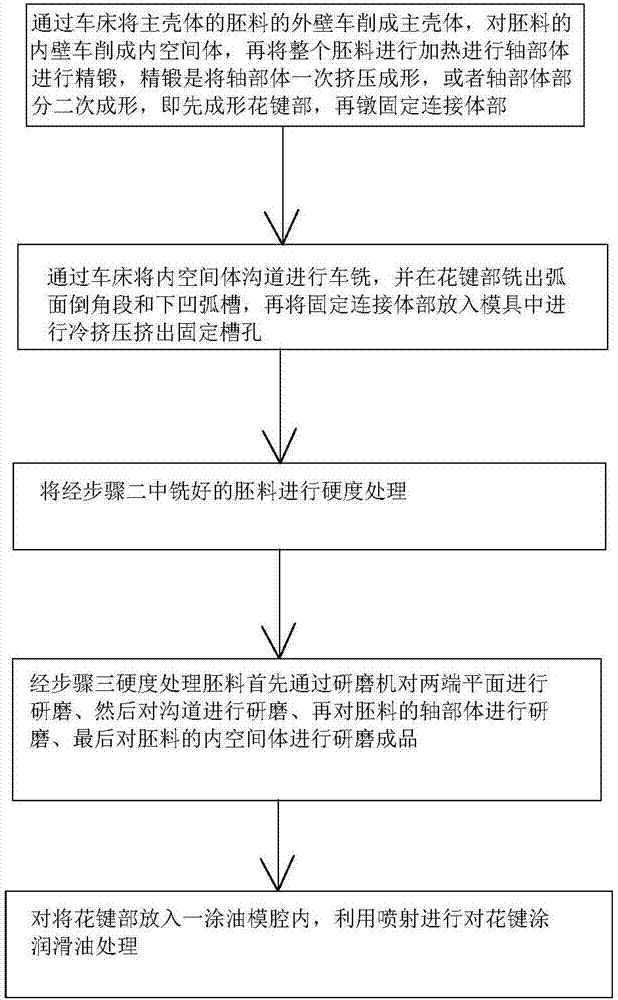
The invention belongs to the technical field of automobile driving accessories, and provides a driving shaft bell-shaped housing structure and a process treatment method of the driving shaft bell-shaped housing structure. The driving shaft bell-shaped housing structure comprises a main housing and a shaft body; each channel chamfer angle is reduced from the left end to the right end; the shaft body comprises a spline part and a fixed connection body part; a cambered chamfer section is arranged between the left end of the spline part and the main housing; and a lower concave arc groove is formed between the right end of the spline part and the fixed connection body part. The process treatment method is characterized in that the inner wall of a blank is lathed into an inner space body, then the whole blank is heated and precision forging of the shaft body is carried out, precision forging means the shaft body is subjected to extrusion forming at one time or is partly subjected to secondary forming, that is the spline part is formed first, and the milled blank is subjected rigidity treatment and a spline is subjected to lubricating oil treatment. The driving shaft bell-shaped housing structure has the advantages that due to the channel chamfer angles, steel balls can be kept in the centers to the greatest extent when the steel balls rotate, the carrying capacity is improved, a situation that ballistic work is lowered due to temper brittleness is avoided, and the integral torque performance is high, thus the rigidity requirement is met.

Description

technical field [0001] The invention belongs to the technical field of automobile drive accessories, and relates to a bell-shaped shell structure of a drive shaft and a processing method thereof. Background technique [0002] In order to transmit the power of the car, the drive axle assembly will be used. At present, the ball cage type drive axle assembly is the most used. Speed ​​transmission problem, and the transmission working angle is large and the efficiency is high. The disadvantage of the existing spherical cage and spherical shell structure is that the internal structure of the entire shell is unreasonable, which causes the car to suffer during the steering process, and brings certain safety hazards during the driving process. At the same time, due to improper processing methods during the process It will lead to the degradation of the performance of the mechanical parts and it is difficult to control and realize in the prior art, and the place where the bell shell...

Claims


Application Information

Patent Timeline
IPC IPC(8): F16D3/22F16D3/84B23P15/14C22C38/02C22C38/04C22C38/42C22C38/44C22C38/46C21D1/18C21D9/00
CPCF16D3/22F16D3/84C21D1/18C21D9/0068C22C38/02C22C38/04C22C38/42C22C38/44C22C38/46B23P15/14F16D2200/0021F16D2250/0053F16D2250/0038C21D2211/002C21D2211/009Y02P10/25
Inventor 叶祥宝
Owner NINGBO V SHINE AUTO PARTS
Why Eureka
Eureka Blog
Learn More