Fan wheel structure of cooling fan

A heat dissipation fan and fan wheel technology, applied in non-variable pumps, pump components, components of pumping devices for elastic fluids, etc., can solve problems such as easy breakage of joints

Active Publication Date: 2019-12-13
ASIA VITAL COMPONENTS SHENZHEN CO LTD
View PDF7 Cites 0 Cited by
  • Summary
  • Abstract
  • Description
  • Claims
  • Application Information

AI Technical Summary

Problems solved by technology

[0004] Another object of the present invention is to provide a blade set whose blades are not directly connected to the hub, but are connected to the hub by a ring cover, so as to fix multiple blades around the hub and improve the conventional direct welding or clamping of the blades and the hub. The problem that the connection is easy to break due to the connection

Method used


Image

  • Fan wheel structure of cooling fan
  • Fan wheel structure of cooling fan
  • Fan wheel structure of cooling fan

Examples


Embodiment approach

[0037] The above-mentioned purpose of the present invention and its structural and functional characteristics will be described based on the preferred embodiments of the accompanying drawings.

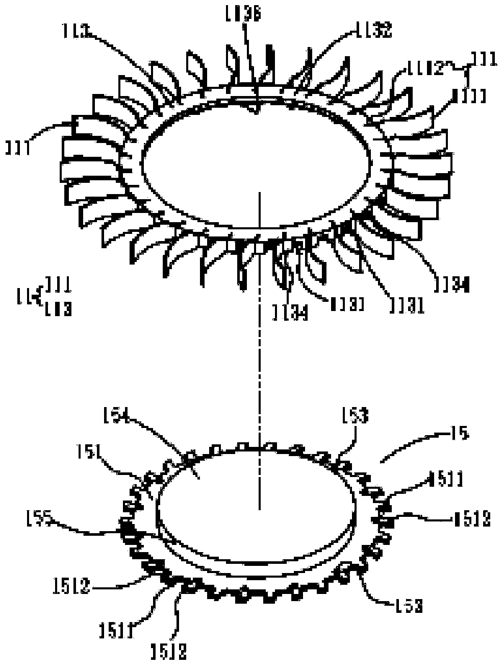
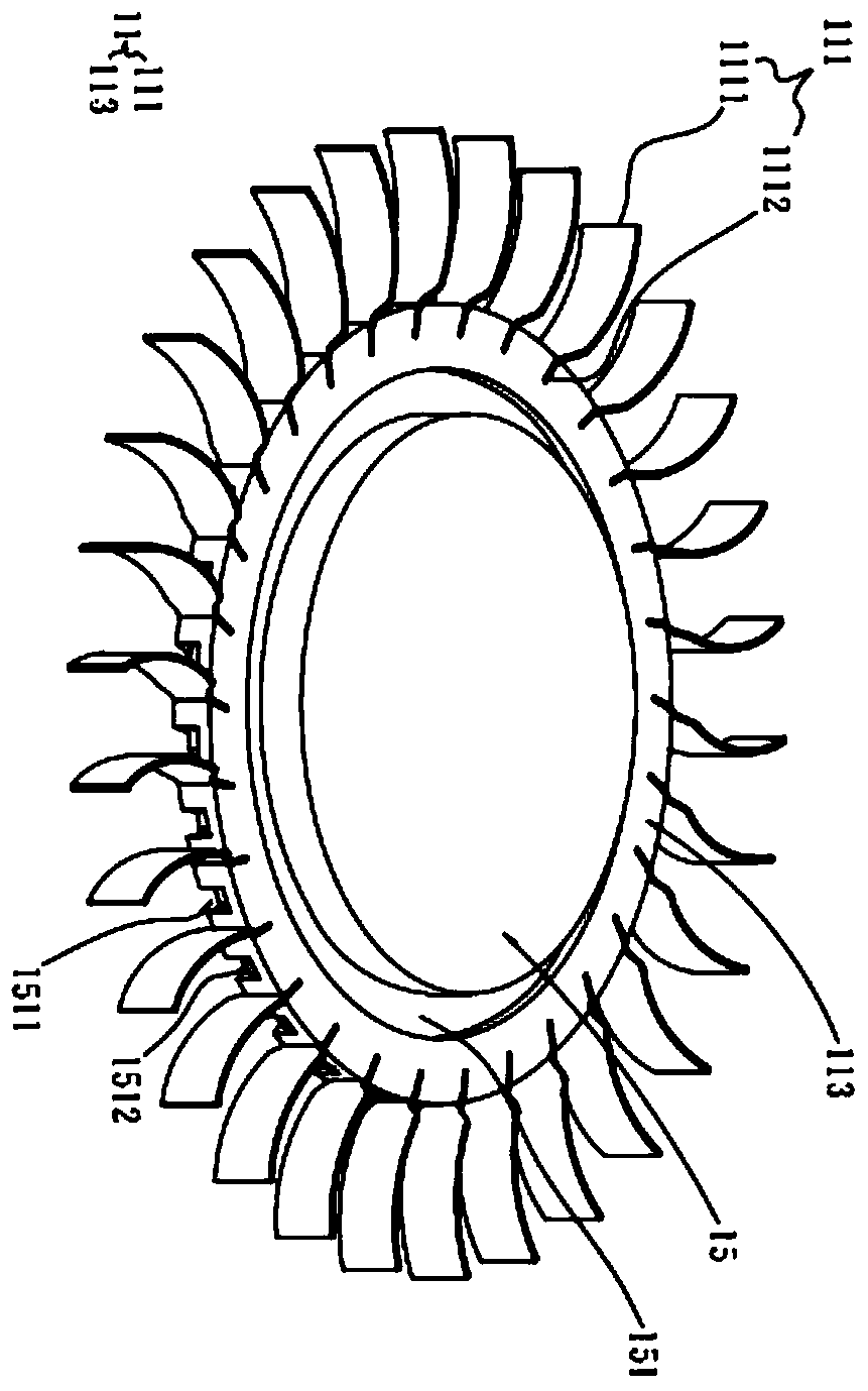
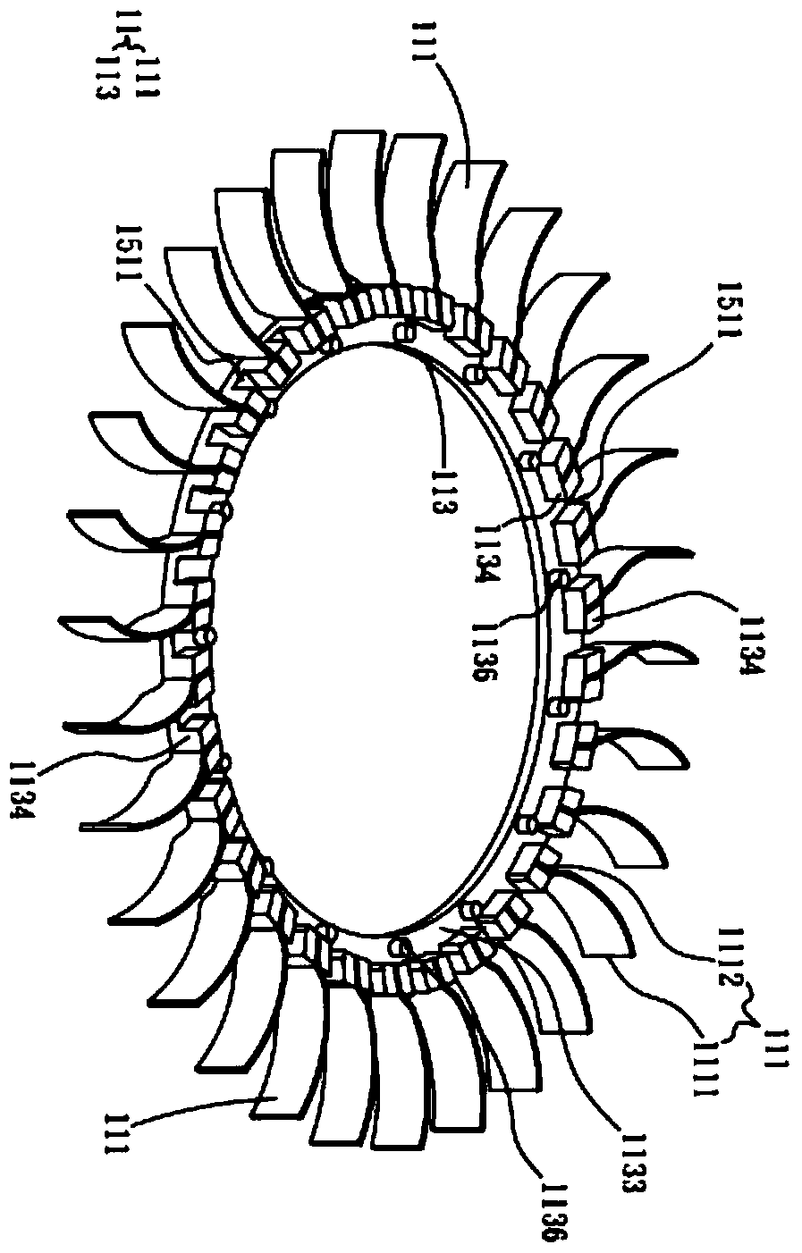
[0038] refer to Figure 1A and Figure 1B It is a three-dimensional schematic diagram of the decomposition and assembly of the first embodiment of the present invention, supplemented by reference image 3 . The present invention provides a fan wheel structure of a cooling fan. The cooling fan in this embodiment is, for example, a centrifugal fan (not shown in the figure). The aforementioned fan wheel structure 1 includes a fan blade set 11 and a hub 15. The fan blade set 11 has a plurality of blades 111 and a ring cover 113. The material of these blades 111 can be a metal material with ductility and good strength. , such as aluminum, aluminum alloy, steel, iron or titanium alloy, but the present invention is not limited thereto. And these blades 111 have a front end 1111, a rear end...


PUM


Abstract

The invention relates to a fan wheel structure of a cooling fan. The structure comprises a fan blade set and a hub; the fan blade set is provided with multiple blades and a ring cover body; the ring cover body and the back ends of the multiple blades are combined as a whole in an integral coating ejecting manner; or the ring cover body and the back ends of the multiple blades are combined as a whole by laser welding; and the ring cover body combined with the multiple blades is correspondingly joined with the hub as a whole.

Description

technical field [0001] The invention relates to a cooling assembly, in particular to a fan wheel structure of a cooling fan. Background technique [0002] The fan is a common part in the field of electronic heat dissipation. It is usually made of metal or plastic. When the blade is made of plastic, it is made by injection molding. Therefore, the thickness of the blade is usually greater than 0.3mm. Moreover, due to the characteristics of the plastic material, the blade should not be too Thin to avoid the wind resistance when the blade cannot withstand the rotation. Therefore, reducing the thickness of the blades to make them ultra-thin blades with considerable strength, and how to combine the ultra-thin blades with the hub of the fan, are currently the efforts of those skilled in the art. Contents of the invention [0003] Therefore, in order to effectively solve the above-mentioned problems, the main purpose of the present invention is to provide a fan wheel structure of...

Claims


Application Information

Patent Timeline
Patent Type & Authority Patents(China)
IPC IPC(8): F04D25/08F04D29/30
CPCF04D25/08F04D29/30
Inventor 徐亮华王得中
Owner ASIA VITAL COMPONENTS SHENZHEN CO LTD
Why Eureka
Try Eureka