
Signal transmitting device, receiving device and method and system for synchronizing symbol timing

A technology for receiving equipment and signals, which is applied in the field of signal sending equipment, receiving equipment and symbol timing synchronization, and can solve the problems of low precision of crystal oscillator, large frequency deviation of terminals, and high complexity of symbol timing synchronization

Active Publication Date: 2019-09-03
HUAWEI TECH CO LTD
View PDF9 Cites 0 Cited by
  • Summary
  • Abstract
  • Description
  • Claims
  • Application Information

AI Technical Summary

Problems solved by technology

[0008] In view of this, an embodiment of the present invention provides a signal sending device, a receiving device, and a method and system for symbol timing synchronization to solve the problem that terminals with low crystal oscillator precision have large frequency offsets, resulting in high complexity in symbol timing synchronization The problem

Method used


Image

  • Signal transmitting device, receiving device and method and system for synchronizing symbol timing
  • Signal transmitting device, receiving device and method and system for synchronizing symbol timing
  • Signal transmitting device, receiving device and method and system for synchronizing symbol timing

Examples


example 1

[0268] N1=N2=1, the first signal includes the first generalized ZC sequence with u=1, the second signal includes the second generalized ZC sequence, and the root index of the second generalized ZC sequence is used to distinguish different cells or cell groups.

[0269] For example: the cells in the wireless communication system are divided into 3 groups, the cells of the first group correspond to the second generalized ZC sequence of u=-1, the cells of the second group correspond to the second generalized ZC sequence of u=2, and the cells of the third group correspond to the second generalized ZC sequence of u=2. A cell corresponds to the second generalized ZC sequence for u=-2.

example 2

[0271] Similar to Example 1, N1=N2=1, the first signal includes the first generalized ZC sequence of u=1, the second signal includes the second generalized ZC sequence, and the root index of the second generalized ZC sequence is used to distinguish different A district or group of districts.

[0272] Similarly, the cells in the wireless communication system can be divided into 3 groups. The difference from Example 1 is that: the first group of cells corresponds to the generalized ZC sequence of u=-1, and the second group of cells corresponds to the generalized ZC sequence of u=0.5 , the third group of cells corresponds to the generalized ZC sequence of u=-0.5.

example 3

[0274] The second signal in the synchronization signal includes a plurality of generalized ZC sequences, and the relative positions (time domain positions and / or frequency domain positions) between the plurality of generalized ZC sequences are used to distinguish cells or cell groups, that is, different cells or cell groups Corresponding to different above relative positions.

[0275] For example: when the second signal in the synchronization signal includes three generalized ZC sequences, the root indices of the three generalized ZC sequences are respectively u=1, -1, and 2, and the three generalized ZC sequences are continuously arranged in the time domain.

[0276] like Figure 5D As shown, the cells in the wireless communication system are divided into three groups, and the order of the three generalized ZC sequences corresponding to the cells in the first group is: the generalized ZC sequence with the root index of 1, the generalized ZC sequence with the root index of -1,...


PUM


Abstract

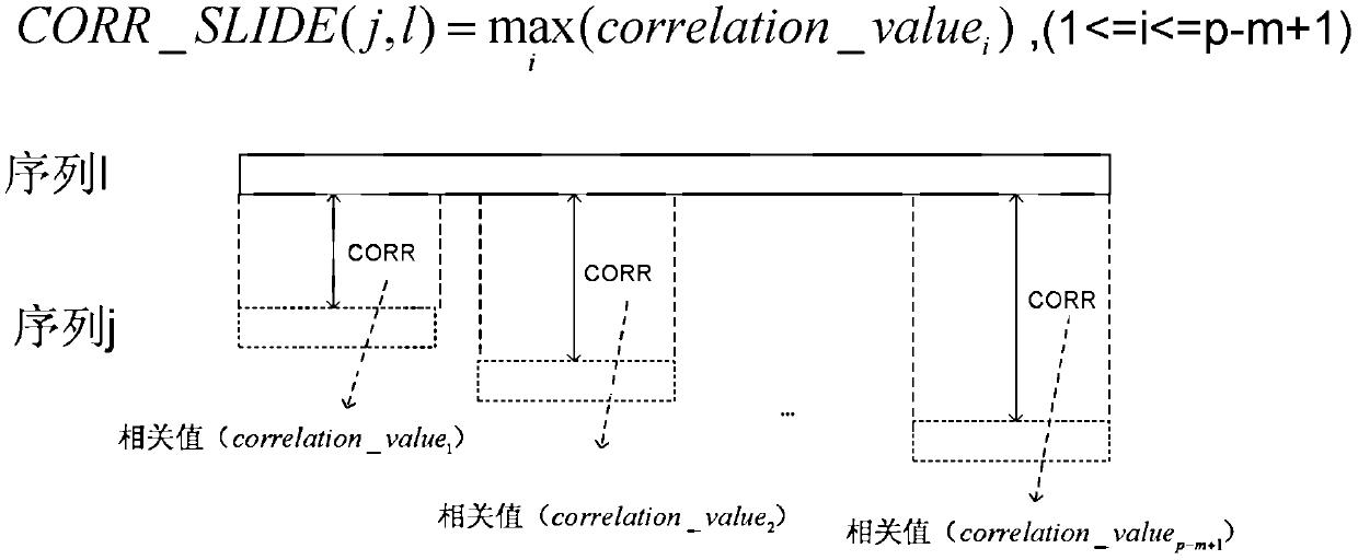
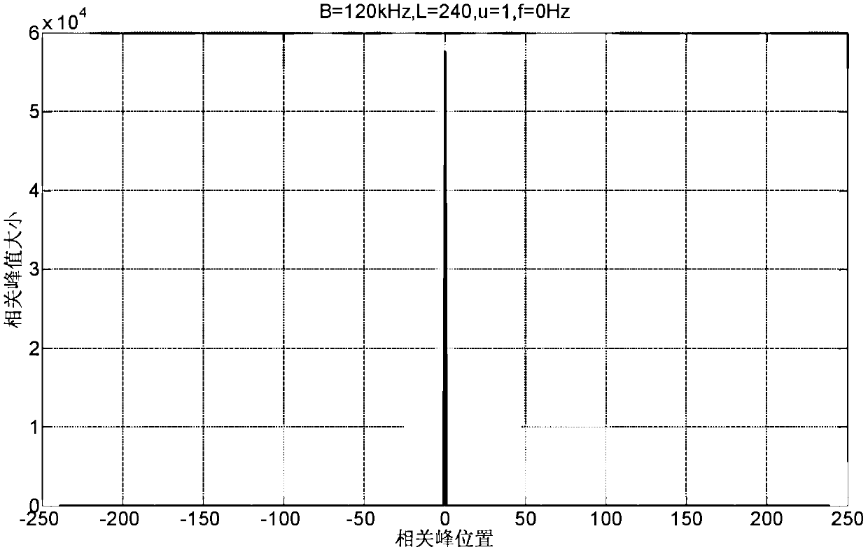
The invention relates to the technical field of wireless communication, and relates to signal sending and receiving equipment, a symbol timing synchronization method and a system, and solves the problem of high complexity of symbol timing synchronization of terminals with low crystal oscillator precision. In a receiving device, the receiving module receives a synchronization signal including a first signal and a second signal, the first signal includes N1 generalized ZC sequences; the second signal includes N2 generalized ZC sequences, which are used to distinguish different cells or different cell group. There are at least two generalized ZC sequences with different root indices in N1+N2 generalized ZC sequences; the processing module performs the first sliding correlation operation and the second sliding correlation operation on the synchronization signal; according to N1 generalized ZC sequences and N2 generalized ZC The relationship between the sliding correlation peaks generated by the sequence during sliding correlation is used for symbol timing synchronization. Compared with the current method that requires multiple grid searches to compensate for large phase rotations, the implementation complexity is low.

Description

technical field [0001] The present invention relates to the technical field of wireless communication, in particular to a signal sending device, a receiving device, and a method and system for synchronizing symbol timing. Background technique [0002] With the rapid development of machine-to-machine (M2M) communication technology, its market demand and scale have shown explosive growth in recent years. [0003] M2M service terminals are faced with the challenge of low power consumption and low cost. Due to cost constraints, the crystal oscillator precision of M2M terminals is low, which will cause a large frequency offset between M2M terminals and communication peers (such as base stations). Frequency offset will cause the phase rotation of the signal in the time domain. [0004] In a Long Term Evolution (LTE) system, a Zadoff-Chu (ZC) sequence is used as a primary synchronization sequence to perform symbol timing synchronization and carrier frequency offset estimation. ...

Claims


Application Information

Patent Timeline
IPC IPC(8): H04W56/00
CPCH04W56/00H04J11/0069H04J13/0062H04L27/2657H04L27/2663H04L27/2671H04W56/001H04W4/70H04L7/041H04L27/2662
Inventor 汲桐吴毅凌于光炜罗伯特·威廉·扬布莱恩·马丁·加夫尼
Owner HUAWEI TECH CO LTD
Learn More