Power reception device, and contactless power transmission device provided with same

A power receiving device, non-contact technology, applied in circuit devices, battery circuit devices, transmission systems, etc., can solve problems such as difficulty in reducing power transmission efficiency

Inactive Publication Date: 2017-08-29
PANASONIC INTELLECTUAL PROPERTY MANAGEMENT CO LTD
View PDF6 Cites 3 Cited by
  • Summary
  • Abstract
  • Description
  • Claims
  • Application Information

AI Technical Summary

Problems solved by technology

The magnetic flux output from this auxiliary coil interlinks with the secondary coil, so the power transmission efficiency hardly decreases

Method used


Image

  • Power reception device, and contactless power transmission device provided with same
  • Power reception device, and contactless power transmission device provided with same
  • Power reception device, and contactless power transmission device provided with same

Examples


Embodiment approach

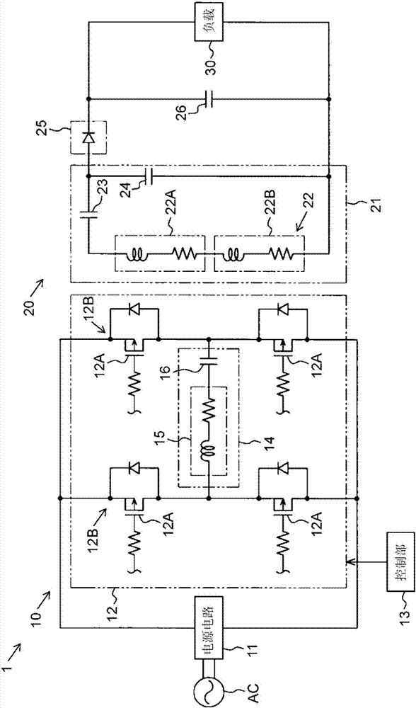
[0051] figure 1 It is a circuit diagram of the non-contact power transmission device according to this embodiment. refer to figure 1Next, the configuration of the non-contact power transmission device 1 will be described.

[0052] The non-contact power transmission device 1 includes: a power transmission device 10 connected to an alternating current power supply AC; a power reception device 20 that receives electric power transmitted from the power transmission device 10; electrical connection.

[0053] The power transmission device 10 includes a power supply circuit 11 that is electrically connected to an AC power supply AC and converts the AC power of the AC power supply AC into DC power. The switch circuit 12 is connected to the power supply circuit 11 , and the switch circuit 12 converts the DC power generated by the power supply circuit 11 into AC power of a preset frequency.

[0054] The switch circuit 12 has two arms 12B connected in parallel. The arm 12B is compos...


PUM


Abstract

A power reception device (1), provided with a plurality of secondary coils (22) interlinking with a magnetic flux outputted by a primary coil (15), and at least one power-reception-side capacitor (23, 24) electrically connected to the secondary coils (22), the power reception device (1) contactlessly receiving power from a power transmission device (10) having the primary coil (15). The secondary coils (22) are serially connected. The center axes of the secondary coils (22) are oriented in different directions. The secondary coils (22) and the power-reception-side capacitor (23, 24) constitute a single power-reception-side resonance circuit (21). The present embodiment makes it possible to easily design the power-reception-side resonance circuit and minimize any decrease in the power transmission efficiency.

Description

technical field [0001] The invention relates to a non-contact power transmission device, especially a power receiving device of the non-contact power transmission device. Background technique [0002] Recently, there is known a non-contact power transmission device that transmits power from a power transmission device to a power reception device by interlinking magnetic flux output from a primary coil of the power transmission device with a secondary coil of the power reception device. [0003] In the non-contact power transmission device, the efficiency of non-contact power transmission (hereinafter referred to as power transmission) from the power transmission device to the power reception device changes according to the direction of the secondary coil relative to the primary coil, so the direction of power transmission Strong. [0004] Development of such a non-contact power transmission device is underway that can suppress a decrease in power transmission efficiency whe...

Claims


Application Information

Patent Timeline
Patent Type & Authority Applications(China)
IPC IPC(8): H02J50/00H01F27/28H02J7/00
CPCH01F2003/005H02J50/12H01F38/14H04B5/0037B60L53/122Y02T10/70Y02T10/7072Y02T90/14B60L53/12H01F27/28
Inventor 筒井真美北村浩康松木英敏佐藤文博太田佑贵青木秀太
Owner PANASONIC INTELLECTUAL PROPERTY MANAGEMENT CO LTD
Why Eureka
Try Eureka