Closed unit of an injection molding machine with pillars

A technology for injection molding machines and pillars, which is applied in the direction of fluid pressure actuating devices, etc., and can solve the problems of friction loss, excessive wear, friction surface pollution, etc. between the clamping sleeve and the pillar

Active Publication Date: 2020-06-02
KRAUSSMAFFEI TECH GMBH
View PDF8 Cites 0 Cited by
  • Summary
  • Abstract
  • Description
  • Claims
  • Application Information

AI Technical Summary

Problems solved by technology

However the disadvantage is that due to the necessary high oil volume (long oil column) a significant disadvantage in terms of energy consumption has to be endured
[0006] A disadvantage in such a clamping device is that various kinds of impurities such as water, cooling water, dirt, grease, parting agents and the like may reach between the clamping sleeve and the part to be clamped due to the movement of the pillar. between the strut areas, whereby an unintended loss of friction or excessive wear between the clamping sleeve and the struts may occur
Such clamping heads have the same disadvantages as described above for WO 2010 / 109374 A1
Risk of contamination of the friction surfaces between the clamping sleeve and the corresponding surface of the strut

Method used


Image

  • Closed unit of an injection molding machine with pillars
  • Closed unit of an injection molding machine with pillars
  • Closed unit of an injection molding machine with pillars

Examples


Embodiment Construction

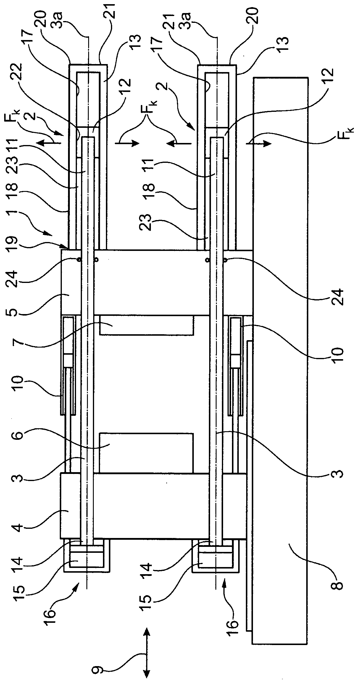
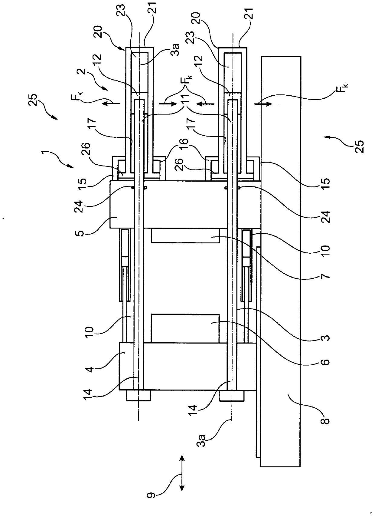
[0031] figure 1Shown is a closing unit 25 according to the invention of an injection molding machine 1 with a clamping locking device 2 according to the invention. The injection molding machine 1 has columns 3 which are each equipped with a clamping locking device 2 . The injection molding machine 1 has a first mold clamping plate 4 and a second mold clamping plate 5, wherein a first mold half 6 is arranged on the first mold clamping plate 4 and a second mold clamping plate 5 There is a second mold half 7 . exist figure 1 In the preferred embodiment, the first mold clamping plate 4 is a movable mold clamping plate. The second mold clamping plate 5 is a fixed mold clamping plate. The movable first mold clamping plate 4 is mounted displaceably in the opening and closing direction 9 relative to the machine base 8 by means of actuator cylinders 10 . Of Course Injection Molding Machine 1 figure 1 The illustrated embodiment is not limited to the actuating cylinder 10 for openi...


PUM


Abstract

A clamping unit of an injection molding machine having platens and columns includes a clamping-type locking apparatus by which a column is securable in relation to one of the platens at any position along a travel path of the platens relative to one another. The clamping-type locking apparatus includes a clamping jacket and a clamping device for clamping-type locking of the column in relation to the clamping jacket. The clamping device is displaceable together with the column along the travel path within the clamping jacket, when the clamping device assumes a released state, and the clamping device is configured to effect a clamping action by generating between the clamping jacket and the clamping device a locking force which is directed radially outwards in relation to a longitudinal axis of the column.

Description

technical field [0001] The invention relates to a closed unit of an injection molding machine with a column. Background technique [0002] It is known in the prior art, for example, to equip closing units for double-plate injection molding machines with short-stroke cylinders, such as pressure pads, in order to generate the closing force, and to implement mechanically between the support and the mold for the transmission of the closing force. Locking between clamping plates. In this case, in particular locking by means of a positive fit is common, wherein the strut has teeth in certain regions, into which the locking device can be folded or inserted, so that the mold clamping plate and the A positive connection is produced between the struts. [0003] Such hydrodynamic principles are established and proven as standard in high closure force situations. In the area of ​​low closing forces, such a system has a cost disadvantage, since a large number of components are require...

Claims


Application Information

Patent Timeline
Patent Type & Authority Patents(China)
IPC IPC(8): B29C45/67F15B15/26
CPCB29C45/6728F15B15/262B29C2045/6757
Inventor D·阿默尔P·施韦斯塔尔
Owner KRAUSSMAFFEI TECH GMBH
Why Eureka
Try Eureka