Shock-resistant ball valve
A technology of impact resistance and ball valves, which is applied in the field of impact resistance ball valves, can solve the problems of poor wear resistance, aging resistance, and easy damage, etc., and achieve the effect of good wear resistance
- Summary
- Abstract
- Description
- Claims
- Application Information
AI Technical Summary
Problems solved by technology
Method used
Image

Examples
Embodiment 1
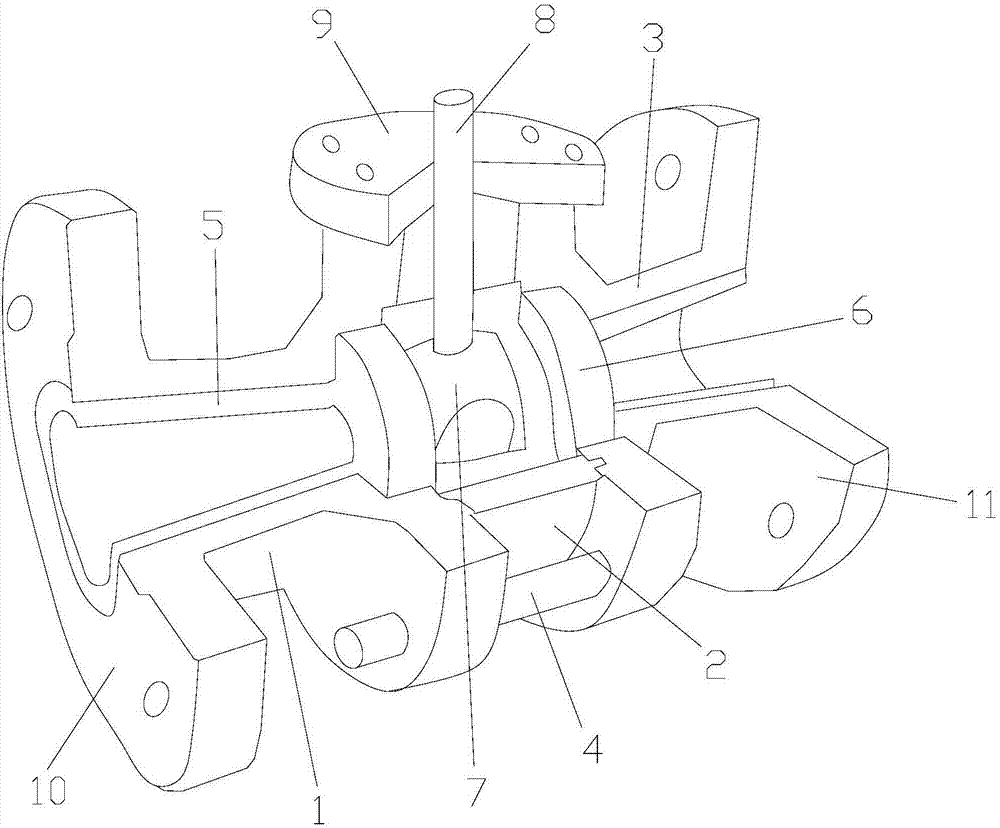
[0023] An impact-resistant ball valve includes a first valve body 1, a rubber cylinder 2 and a second valve body 3, the rubber cylinder 2 is arranged between the first valve body 1 and the second valve body 3, the first valve body The body 1 and the second valve body 3 are fixed by bolts 4, the first valve body 1 and the second valve body 3 are provided with a polyurethane sleeve 5, the polyurethane sleeve 5 is arranged in a trumpet shape, and the middle part of the polyurethane sleeve 5 A valve seat 6 is provided, the valve seat 6 is integrally formed with the polyurethane sleeve 5, a ball head 7 is installed inside the valve seat 6, a valve stem 8 is fixed on the top of the ball head 7, and the valve stem 8 is provided with End cover 9, said end cover 9 is fixedly connected with first valve body 1 and second valve body 3 respectively, said valve stem 8 runs through the middle part of valve cover 9, said first valve body 1 is welded with a first flange 10. A second flange 11 ...
Embodiment 2
[0033]An impact-resistant ball valve includes a first valve body 1, a rubber cylinder 2 and a second valve body 3, the rubber cylinder 2 is arranged between the first valve body 1 and the second valve body 3, the first valve body The body 1 and the second valve body 3 are fixed by bolts 4, the first valve body 1 and the second valve body 3 are provided with a polyurethane sleeve 5, the polyurethane sleeve 5 is arranged in a trumpet shape, and the middle part of the polyurethane sleeve 5 A valve seat 6 is provided, the valve seat 6 is integrally formed with the polyurethane sleeve 5, a ball head 7 is installed inside the valve seat 6, a valve stem 8 is fixed on the top of the ball head 7, and the valve stem 8 is provided with End cover 9, said end cover 9 is fixedly connected with first valve body 1 and second valve body 3 respectively, said valve stem 8 runs through the middle part of valve cover 9, said first valve body 1 is welded with a first flange 10. A second flange 11 i...
Embodiment 3
[0043] An impact-resistant ball valve includes a first valve body 1, a rubber cylinder 2 and a second valve body 3, the rubber cylinder 2 is arranged between the first valve body 1 and the second valve body 3, the first valve body The body 1 and the second valve body 3 are fixed by bolts 4, the first valve body 1 and the second valve body 3 are provided with a polyurethane sleeve 5, the polyurethane sleeve 5 is arranged in a trumpet shape, and the middle part of the polyurethane sleeve 5 A valve seat 6 is provided, the valve seat 6 is integrally formed with the polyurethane sleeve 5, a ball head 7 is installed inside the valve seat 6, a valve stem 8 is fixed on the top of the ball head 7, and the valve stem 8 is provided with End cover 9, said end cover 9 is fixedly connected with first valve body 1 and second valve body 3 respectively, said valve stem 8 runs through the middle part of valve cover 9, said first valve body 1 is welded with a first flange 10. A second flange 11 ...
PUM
 Abstract
Description
Claims
Application Information
 - R&D
- Intellectual Property
- Life Sciences
- Materials
- Tech Scout
- Unparalleled Data Quality
- Higher Quality Content
- 60% Fewer Hallucinations
Browse by: Latest US Patents, China's latest patents, Technical Efficacy Thesaurus, Application Domain, Technology Topic, Popular Technical Reports.
© 2025 PatSnap. All rights reserved.Legal|Privacy policy|Modern Slavery Act Transparency Statement|Sitemap|About US| Contact US: help@patsnap.com