
Industrial exhaust gas and suspended particulate matter purifying processing system

A technology for purification and treatment of industrial waste gas, which is applied in the fields of climate change adaptation, climate sustainability, and dispersed particle separation. Low cost, good purification effect and less equipment investment

Inactive Publication Date: 2017-08-29
熊恒斌
View PDF8 Cites 6 Cited by
  • Summary
  • Abstract
  • Description
  • Claims
  • Application Information

AI Technical Summary

Problems solved by technology

The disadvantages are: huge equipment, large investment, dust removal efficiency is greatly affected by the specific resistance of dust, mainly to remove large particles above PM10, the removal efficiency of particles below PM10 is low, and it cannot remove harmful gases. Equipment with 95% desulfurization and denitrification capacity
The country's huge investment in fog and haze reduction for many years is also due to the limitations of technology and equipment capabilities, which has little effect and cannot achieve the expected results. It is difficult to meet the requirements of the atmospheric environment. Although the country has to reluctantly shut down and relocate some polluting enterprises, because there is no very effective purification technology support, it is still not possible to fundamentally control and treat a wide range of pollution sources in a comprehensive, real and effective manner. Cause production, life, economy, and national health to continue to suffer heavy losses and damage

Method used


Image

  • Industrial exhaust gas and suspended particulate matter purifying processing system
  • Industrial exhaust gas and suspended particulate matter purifying processing system
  • Industrial exhaust gas and suspended particulate matter purifying processing system

Examples


Embodiment

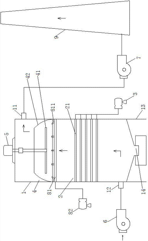
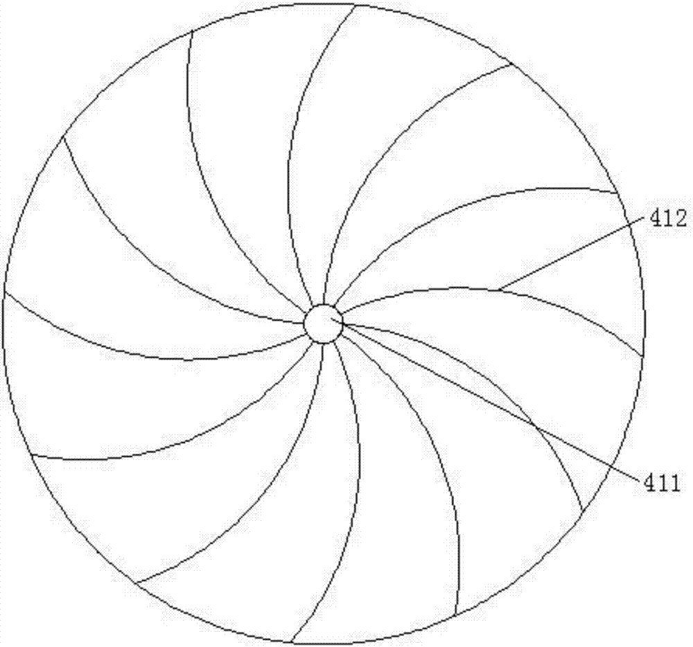
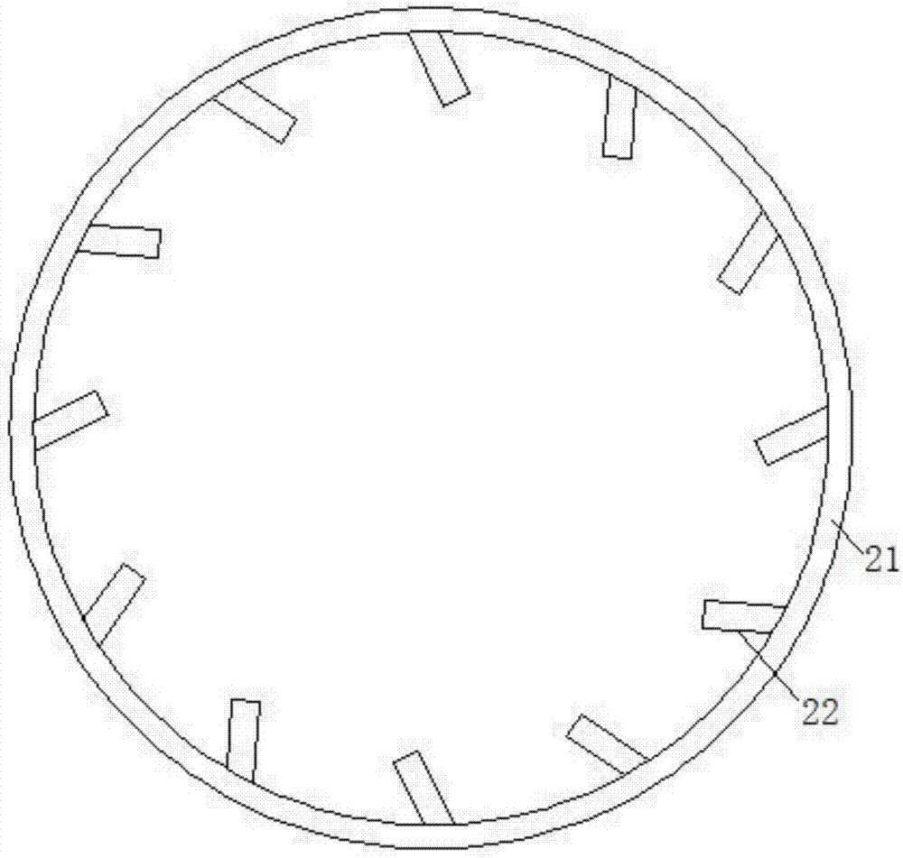
[0048] Example: such as figure 1 , 3 As shown, the industrial waste gas and suspended particulate matter purification treatment system of this embodiment includes a purification cylinder 1, an atomization spray system, a dynamic physical aerosol separation system, a suction device 6 and an exhaust device 7;

[0049] The above-mentioned purification cylinder 1 is a cylindrical structure with a hollow inside. The above-mentioned cylindrical structure has a top wall and a bottom wall, and an air outlet 11 is provided on the upper side wall, and an air inlet 12 is provided on the lower side wall;

[0050] The atomization shower system includes an atomization shower mechanism 2 and a spray pump 3, the atomization shower mechanism 2 is arranged on the inner wall of the purification cylinder 1 and is close to the air inlet, and the spray pump 3 is connected to the atomization nozzle shower mechanism 2;

[0051] The above-mentioned dynamic physical aerosol separation system includes...


PUM

PropertyMeasurementUnit
dust removal efficiencyaaaaaaaaaa

Abstract

The invention relates to an industrial exhaust gas and suspended particulate matter purifying processing system. The industrial exhaust gas and suspended particulate matter purifying processing system comprises a purifying cylinder, an atomization spraying system, a dynamic physical gas-mist separation system, an air suction device, and an air discharge device; the upper part of the purifying cylinder is provided with a gas outlet, and the lower part is provided with a gas inlet; the atomization spraying system comprises an atomization spraying mechanism, and a spraying pump; the atomization spraying mechanism is arranged on the inner wall of the purifying cylinder close to the gas inlet; the spraying pump is communicated with the atomization spraying mechanism; the dynamic physical gas-mist separation system comprises a dynamic physical gas-mist separation device and a rotating driving device; the dynamic physical gas-mist separation device is arranged on the inner wall of the purifying cylinder close to the gas outlet, and a dynamic physical blocking separating rotor is arranged in the dynamic physical gas-mist separation device; the rotating driving device is arranged on the upper end of the purifying cylinder, and a driving end is connected with the dynamic physical blocking separating rotor after penetrating the top wall of the purifying cylinder; the air suction device is communicated with the gas inlet; the air discharge device is communicated with the gas outlet. The advantages are as following: purifying effect is excellent, purifying of smoke and dust, suspended particulate matters, dust-containing water mist, and harmful gas can be realized, and environment pollution is reduced.

Description

technical field [0001] The invention belongs to the field of environmental protection applications, in particular to a system for purifying and treating industrial waste gas and suspended particles. Background technique [0002] With the rapid development of social economy, the exhaust gas emissions from factories and workshops are increasing day by day, and the urban population is increasing rapidly, and the smoke emissions from commercial and residential buildings are also increasing. In recent years, although the Ministry of Environmental Protection and relevant departments have successively issued relevant emission standards and regulations for various industries, many factories and mines have also carried out further emission control and equipment renewal, but due to the constraints of purification technology, day after day Production and living emissions continue to pollute the atmospheric environment, leading to increasingly serious smog weather, and the geographical ...

Claims


Application Information

Patent Timeline
Patent Type & Authority Applications(China)
IPC IPC(8): B01D50/00
CPCB01D50/40Y02A50/2351
Inventor 熊恒斌
Owner 熊恒斌
Learn More