
An automatic detection method and automatic detection device for traffic index abnormality

A technology of automatic detection and traffic, applied in the field of communication, can solve problems such as multiple false alarms, heavy workload, and impact on timeliness, and achieve the effect of reducing labor costs, improving efficiency, real-time and accuracy assurance

Active Publication Date: 2019-10-01
携程旅游信息技术(上海)有限公司
View PDF5 Cites 0 Cited by
  • Summary
  • Abstract
  • Description
  • Claims
  • Application Information

AI Technical Summary

Problems solved by technology

At present, with the rapid development of their business, some companies with large-scale call centers have exponentially increased the number of call center systems and business lines that need to be monitored. This traditional traffic index data monitoring method can no longer meet the needs of users. need
[0003] Specifically, on the one hand, because the curves of each business line are diversified and do not have uniform characteristics, if tens of thousands of monitoring items are still manually configured one by one, the workload will be huge and the efficiency will be extremely low, and a lot of time will be wasted. Labor costs; and the real-time and accuracy of manual configuration cannot be guaranteed, which also has a great impact on the timeliness of subsequent processing
[0004] On the other hand, each business line of the call center is affected by various objective factors, resulting in more false alarms
For example, some business curves with special time changes (such as holidays or flight changes) will often cause large jitter in traffic index data due to non-business system failures during this special time, resulting in more false alarms
However, the current monitoring methods cannot effectively filter these false alarms, which also has a great impact on the accuracy of monitoring.

Method used


Image

  • An automatic detection method and automatic detection device for traffic index abnormality
  • An automatic detection method and automatic detection device for traffic index abnormality
  • An automatic detection method and automatic detection device for traffic index abnormality

Examples


Embodiment Construction

[0031] Example embodiments will now be described more fully with reference to the accompanying drawings. Example embodiments may, however, be embodied in many forms and should not be construed as limited to the embodiments set forth herein; rather, these embodiments are provided so that this disclosure will be thorough and complete, and will fully convey the concept of example embodiments to those skilled in the art. The same reference numerals denote the same or similar structures in the drawings, and thus their repeated descriptions will be omitted.

[0032] The described features, structures, or characteristics may be combined in any suitable manner in one or more embodiments. In the following description, numerous specific details are provided in order to give a thorough understanding of embodiments of the invention. However, those skilled in the art will appreciate that the technical solutions of the present invention may be practiced without one or more of the specific...


PUM


Abstract

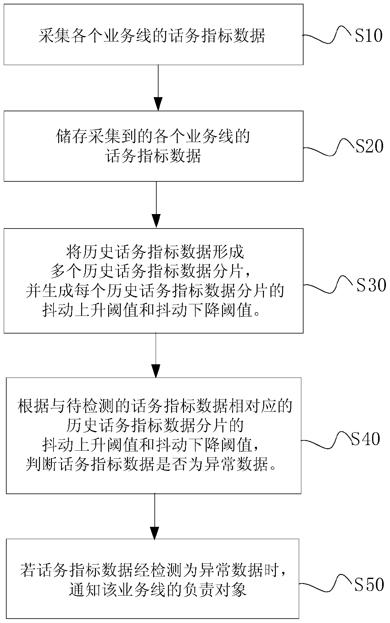
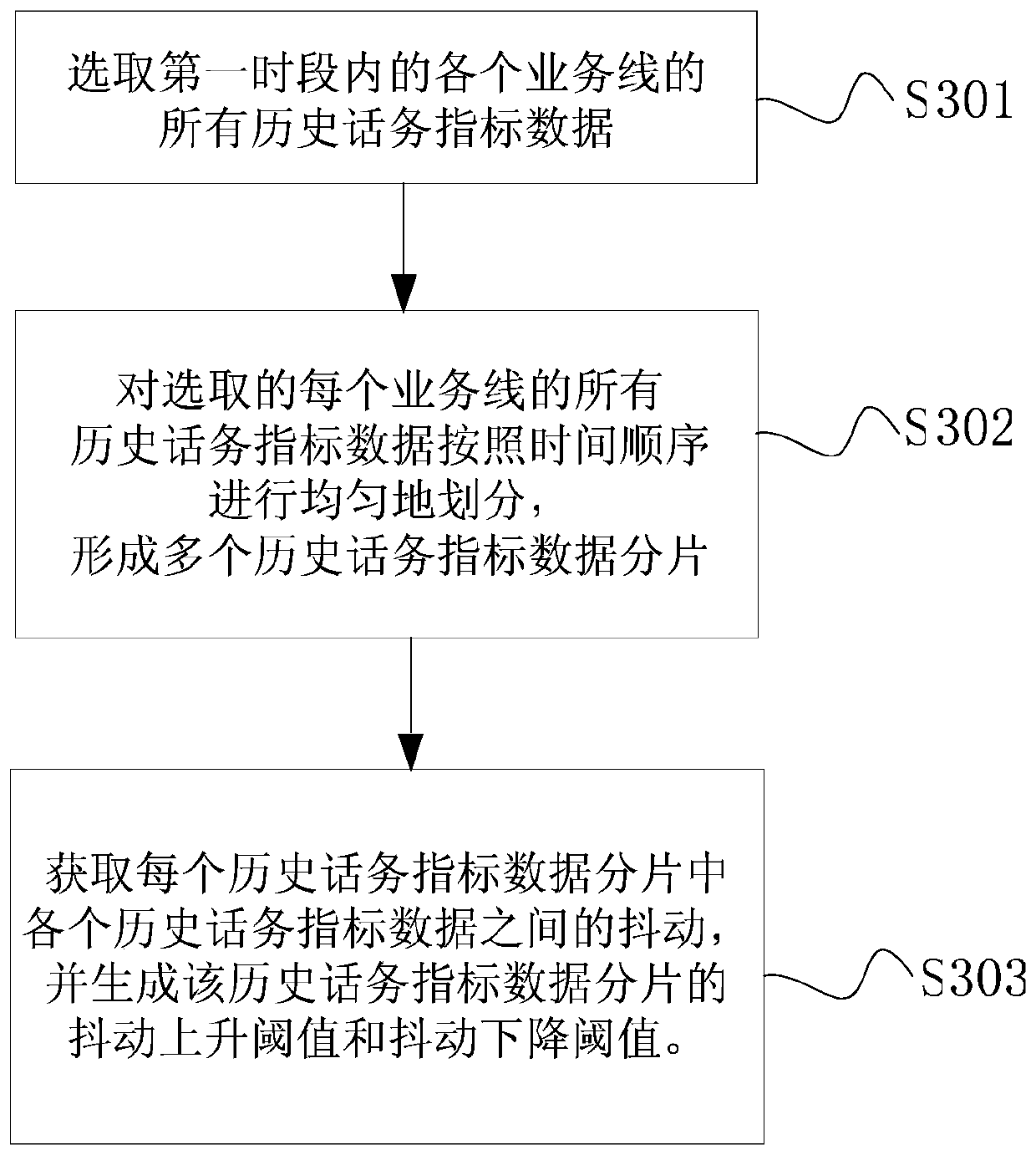
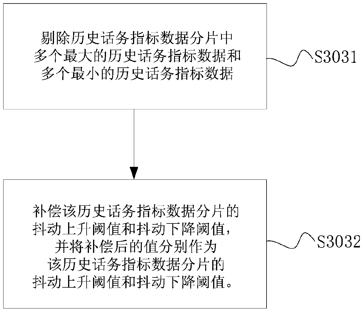
The invention discloses an automatic detection method and an automatic detection device for a traffic index abnormality, terminal equipment ad a storage medium. The automatic detection method for the traffic index abnormality comprises the following steps of: acquiring traffic index data of each service line; storing the acquired traffic index data of each service line; forming a plurality of historical traffic index data fragments by the stored historical traffic index data of each service line according to a time dimension, and generating a jitter rising threshold and a jitter falling threshold of each historical traffic index data fragment; according to the jitter rising threshold and the jitter falling threshold of the historical traffic index data fragment corresponding to traffic index data to be detected, judging whether the traffic index data is abnormal data; and when the traffic index data is detected as the abnormal data, after carrying out processing on warning contents of a service line where the traffic index data is positioned, notifying a responsible object of the service line.

Description

technical field [0001] The invention relates to the field of communication technology, in particular to an automatic detection method for abnormal traffic indicators in a call center, an automatic detection device for abnormal traffic indicators, terminal equipment, and a storage medium. Background technique [0002] The existing call center monitoring platform monitors the traffic index data of each business line, but the monitoring method is generally to manually configure each monitoring item one by one. At present, with the rapid development of their business, some companies with large-scale call centers have exponentially increased the number of call center systems and business lines that need to be monitored. This traditional traffic index data monitoring method can no longer meet the needs of users. need. [0003] Specifically, on the one hand, because the curves of each business line are diversified and do not have uniform characteristics, if tens of thousands of mo...

Claims


Application Information

Patent Timeline
Patent Type & Authority Patents(China)
IPC IPC(8): H04M3/28H04M3/22
Inventor 杜鹃朱挺
Owner 携程旅游信息技术(上海)有限公司
Learn More