Electromagnetic-piezoelectric composite type wave energy collection device

A collection device and composite technology, applied in the direction of battery circuit devices, circuit devices, generators/motors, etc., can solve the problems of poor energy collection effect, large impact of transmission gear transmission, complex overall structure, etc.

Active Publication Date: 2017-08-22
SOUTHWEST JIAOTONG UNIV
View PDF11 Cites 4 Cited by
  • Summary
  • Abstract
  • Description
  • Claims
  • Application Information

AI Technical Summary

Problems solved by technology

[0003] According to the search, there are currently existing self-powered devices that collect vibration energy, such as "A Portable Piezoelectric-Electromagnetic Hybrid Power Generation Device Accelerated by Variable Gears" disclosed in Chinese Patent Application No. 201510881581.9. Although the hybrid power generation device described in this patent It can realize the conversion of functional energy into electric energy in the field or in emergency situations, but due to the large impact of the transmission gear used in it, a large dynamic load is generated, and the gear transmission unit generates charges by hitting the piezoelectric ceramic power generation unit to damage the piezoelectric ceramic power generation piece In addition, the inve

Method used


Image

  • Electromagnetic-piezoelectric composite type wave energy collection device
  • Electromagnetic-piezoelectric composite type wave energy collection device
  • Electromagnetic-piezoelectric composite type wave energy collection device

Examples


Embodiment Construction

[0029] Below in conjunction with accompanying drawing and specific embodiment the present invention will be described in further detail:

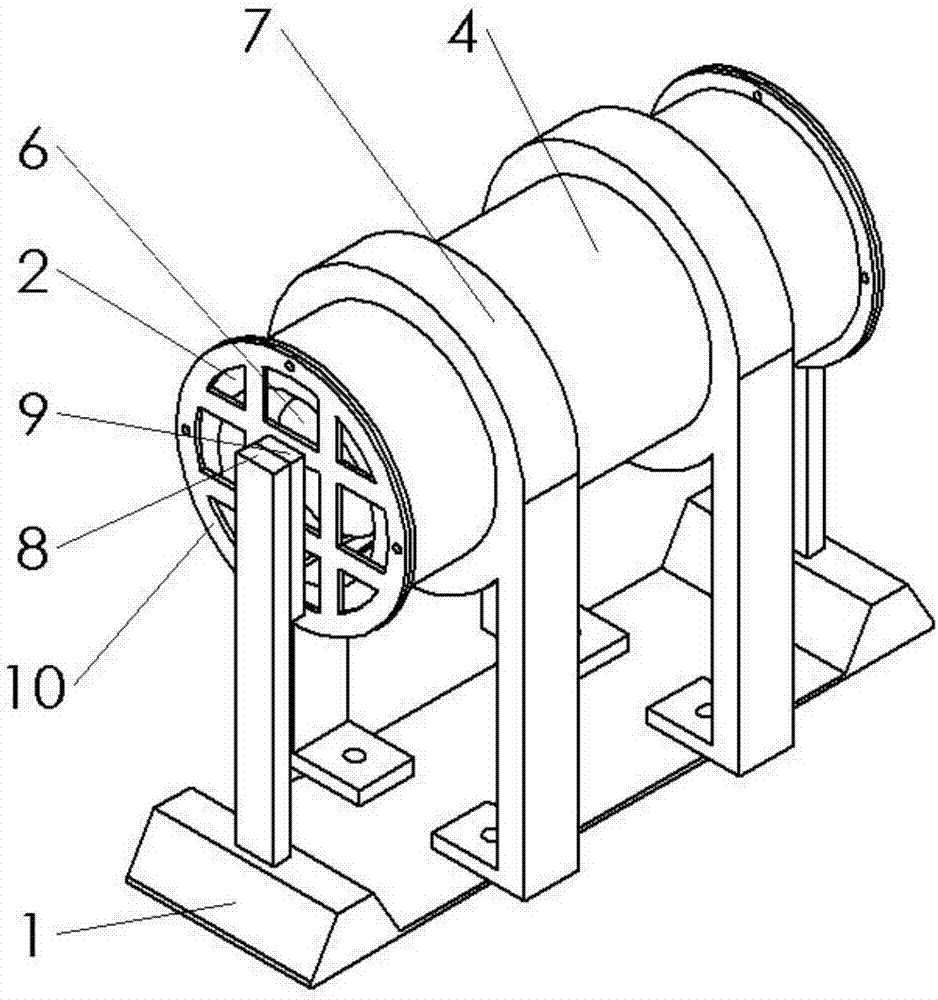
[0030] An electromagnetic piezoelectric composite wave energy harvesting device, comprising:

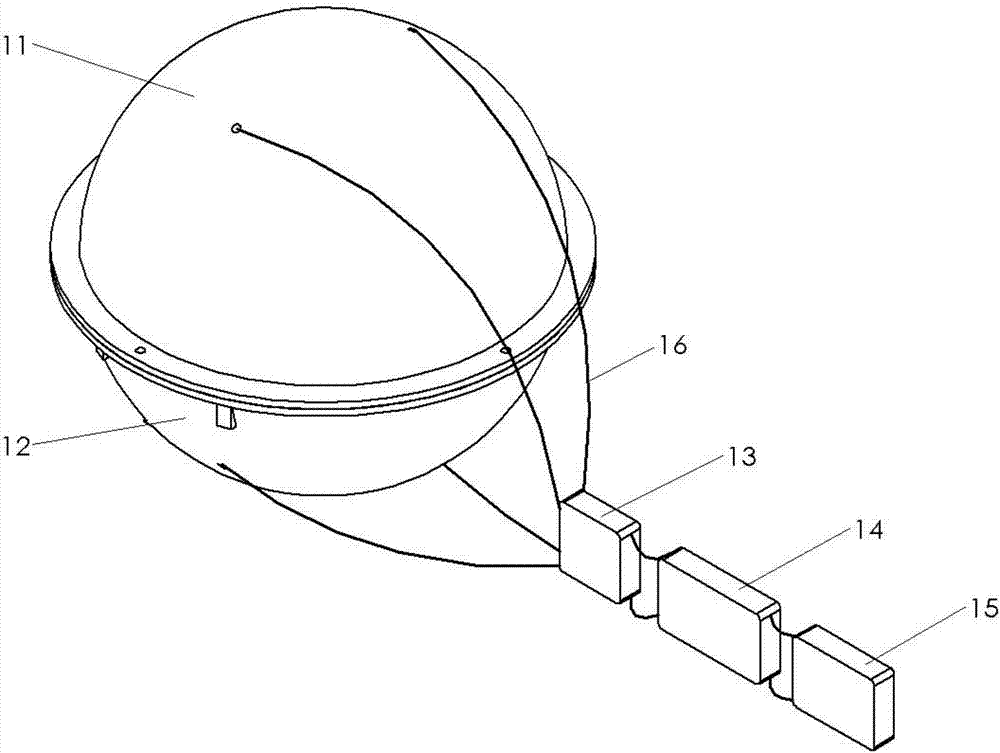
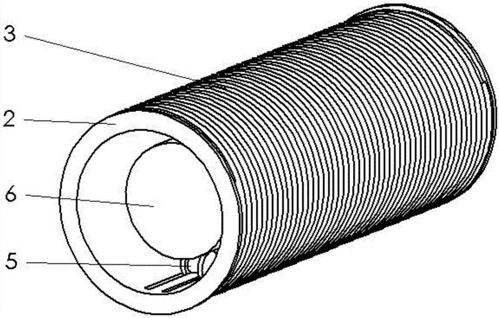
[0031] The device is placed in the spherical shell, and the sealing protection of the device is completed by the upper shell 11. The device is fixed by the circular lower baffle 17 in the lower shell 12 and the two trapezoidal upper baffles 18 in the sealing 11 of the upper shell. The two ends of the base 1 are respectively There is a pair of piezoelectric bimorphs 8, and a pair of rectangular magnets 9 are laid on the inner side of the piezoelectric bimorphs 8. The flat part of the base 1 is provided with two sets of support frames 7 of electromagnetic energy collection structure, and the support frame 7 is arranged in the retaining ring of the support frame 7. The two ends of the cylindrical protection cylinder 4 are respectively fixed by the fl...


PUM


Abstract

The invention provides an electromagnetic-piezoelectric composite type wave energy collection device and belongs to the technical field of designing and manufacturing of energy collection devices. The objective of the invention is to achieve that vibration energy of fluctuated waves are acquired to replace a traditional cell to carry out permanent power supply on micro-devices like ocean monitoring wireless sensors. The wave energy collection device comprises an electromagnetic type energy collection structure and a piezoelectric type energy collection structure. A pair of piezoelectric bimorph cantilever arm structures are arranged on two ends of a base. A pair of rectangular magnets are laid on the piezoelectric bimorphs. Two groups of support racks are arranged on a flat plate part of the base. Two ends of each of cylindrical protection cylinders in the support racks are fixed through flanges and protection nets. The protection cylinders are arranged in the middle parts of the piezoelectric bimorph cantilever arm structures. Coil cylinders are arranged in the protection cylinders. The length of each coil cylinder is consistent with that of the corresponding protection cylinder. Coils are laid on the coil cylinders. Magnetic vibrators are arranged in the coil cylinders. Two pairs of rollers are arranged on upper and lower sides of the magnetic vibrators. The wave energy collection device is mainly used for providing power for ocean wireless sensors.

Description

technical field [0001] The invention belongs to the field of design and manufacture of energy harvesting devices. Background technique [0002] With the development of society, the development of new energy has become an inevitable way of social progress. On the one hand, the energy sources required for industrial and agricultural production are mainly oil, coal, and natural gas. According to the current energy consumption rate, in the near future, oil, coal, natural gas and other energy sources will be exhausted; on the other hand, with the development of science and technology, electronic products are constantly tending to miniaturization and integration, which greatly promote With the rapid development of low-power wireless sensor networks and micro-electromechanical systems, the power supply problem is becoming a great obstacle to their further development. The traditional electrochemical battery power supply method has disadvantages such as short life, frequent replac...

Claims


Application Information

Patent Timeline
IPC IPC(8): H02J7/32H02N2/18
CPCH02N2/186H02J7/32Y02E10/30
Inventor 张祖涛漆令飞杨雯王舒文陈颖顾新壮周启帆
Owner SOUTHWEST JIAOTONG UNIV
Why Eureka
Try Eureka