
Method and system for monitoring state of protection outlet pressure plate based on peripheral auxiliary contacts

A state monitoring system and auxiliary contact technology, applied in the direction of measuring electricity, measuring devices, measuring electrical variables, etc., can solve problems such as high cost, lack of engineering permit conditions, and large engineering volume, and achieve high safety and application prospects Appreciable, good anti-interference ability and reliability effect

Active Publication Date: 2019-07-09
STATE GRID CORP OF CHINA +3
View PDF7 Cites 0 Cited by
  • Summary
  • Abstract
  • Description
  • Claims
  • Application Information

AI Technical Summary

Problems solved by technology

However, this solution is more suitable for the design standards of newly manufactured pressure plates and newly-built screen cabinets in the future. To carry out intelligent pressure plate transformation in the astonishingly large number of screen cabinets that have been put into operation today, on the one hand, the amount of work is large and the cost is high. May also not be eligible for engineering permits

Method used


Image

  • Method and system for monitoring state of protection outlet pressure plate based on peripheral auxiliary contacts
  • Method and system for monitoring state of protection outlet pressure plate based on peripheral auxiliary contacts
  • Method and system for monitoring state of protection outlet pressure plate based on peripheral auxiliary contacts

Examples


Embodiment Construction

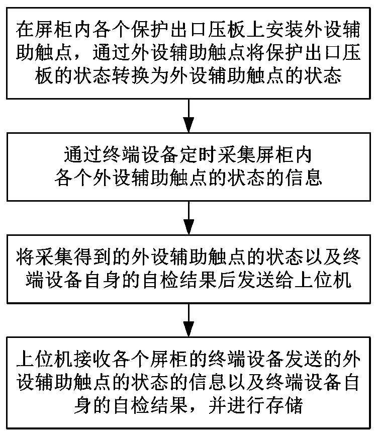
[0036] Such as figure 1 As shown, the implementation steps of the method for monitoring the state of the protection outlet pressure plate based on the peripheral auxiliary contacts in this embodiment include:

[0037] 1) Install peripheral auxiliary contacts on each protection outlet pressure plate in the screen cabinet, and convert the state of the protection outlet pressure plate to the state of the peripheral auxiliary contacts through the peripheral auxiliary contacts;

[0038] 2) Collect the state information of each peripheral auxiliary contact in the screen cabinet regularly through the terminal device, and send the collected state of the peripheral auxiliary contact and the self-test result of the terminal device to the host computer;

[0039] 3) The host computer receives the status information of the peripheral auxiliary contacts sent by the terminal equipment of each panel cabinet and the self-test results of the terminal equipment itself, and sends the status infor...


PUM


Abstract

The invention discloses a protection outlet pressing plate state monitoring method and a protection outlet pressing plate state monitoring system based on peripheral auxiliary contacts. The protection outlet pressing plate state monitoring method is implemented by the steps of: installing the peripheral auxiliary contacts on each protection outlet pressing plate inside a screen cabinet, and converting states of the protection outlet pressing plates into states of the peripheral auxiliary contacts by means of the peripheral auxiliary contacts; and acquiring information of the state of each peripheral auxiliary contact inside the screen cabinet regularly, and transmitting the information to an upper computer for storage. The protection outlet pressing plate state monitoring system comprises an upper computer and at least one monitoring unit, wherein each monitoring unit comprises a pressing plate state detecting module and at least one peripheral auxiliary contact, each pressing plate state detecting module comprises a microprocessor and a communication module, the peripheral auxiliary contacts are connected with the microprocessor, and microprocessors are connected with the upper computer. The protection outlet pressing plate state monitoring method and the protection outlet pressing plate state monitoring system are simple and feasible, the peripheral auxiliary contacts are completely isolated from a relay protection device and high-voltage electrical equipment, the method and the system cannot introduce interference, are high in safety, have good anti-interference ability and reliability, are especially suitable for transformation of the existing equipment, and have promising application prospects.

Description

technical field [0001] The invention relates to a state monitoring technology of a protection outlet pressure plate of a substation, in particular to a method and system for monitoring the state of a protection outlet pressure plate based on peripheral auxiliary contacts. Background technique [0002] With the rapid development and wide application of computer, network communication and database technologies, the automation level of substations has been booming and reaching new peaks, which has greatly improved the efficiency and safety of power grid operation. Relay protection is an important part of the substation automation system, and its device itself has a very high level of automation. However, the relay protection outlet pressure plate still adopts manual on-site verification for status detection, and the level of automation and reliability is low, and it is prone to wrong switching of the pressure plate, causing unnecessary accidents. In recent years, electric powe...

Claims


Application Information

Patent Timeline
Patent Type & Authority Patents(China)
IPC IPC(8): G01R31/04
CPCG01R31/69
Inventor 徐浩欧阳帆王威林鸿志梁文武张磊刘海峰李辉敖非刘宇臧欣许立强陈宏王毕
Owner STATE GRID CORP OF CHINA
Learn More