Eureka AIR delivers breakthrough ideas for toughest innovation challenges, trusted by R&D personnel around the world.

Optical fiber coating layer rotation stripping device

A stripping device and coating technology, applied in the field of optical fiber processing, can solve the problems of the influence of the cladding or even the core, the influence of the laser power output power, the damage of the optical fiber coating, etc., to achieve easy follow-up processing, high stripping efficiency, The effect of continuous peeling

Active Publication Date: 2017-08-18
HUAZHONG UNIV OF SCI & TECH
View PDF4 Cites 12 Cited by
  • Summary
  • Abstract
  • Description
  • Claims
  • Application Information

AI Technical Summary

Problems solved by technology

There are three problems in these existing methods: 1) The coating layer is not completely removed, or the end face is not smooth, which affects the properties of the fiber end face during final fusion; 2) The simple mechanical cutting method has limited control over the cutting accuracy, It is easy to cause scratches and damage to the cladding, especially when high power density is required, it may cause damage to the fiber coating layer, fiber breakage and even core melting, affecting the improvement of laser power and the reproduction of output power; 3) some Removal of the coating by chemical and physical methods will affect and damage the cladding and even the fiber core, and at the same time cannot obtain a more ideal cut surface

Method used


Image

  • Optical fiber coating layer rotation stripping device
  • Optical fiber coating layer rotation stripping device
  • Optical fiber coating layer rotation stripping device

Examples


Embodiment Construction

[0026] In order to make the object, technical solution and advantages of the present invention clearer, the present invention will be further described in detail below in conjunction with the accompanying drawings and embodiments. It should be understood that the specific embodiments described here are only used to explain the present invention, not to limit the present invention. In addition, the technical features involved in the various embodiments of the present invention described below can be combined with each other as long as they do not constitute a conflict with each other.

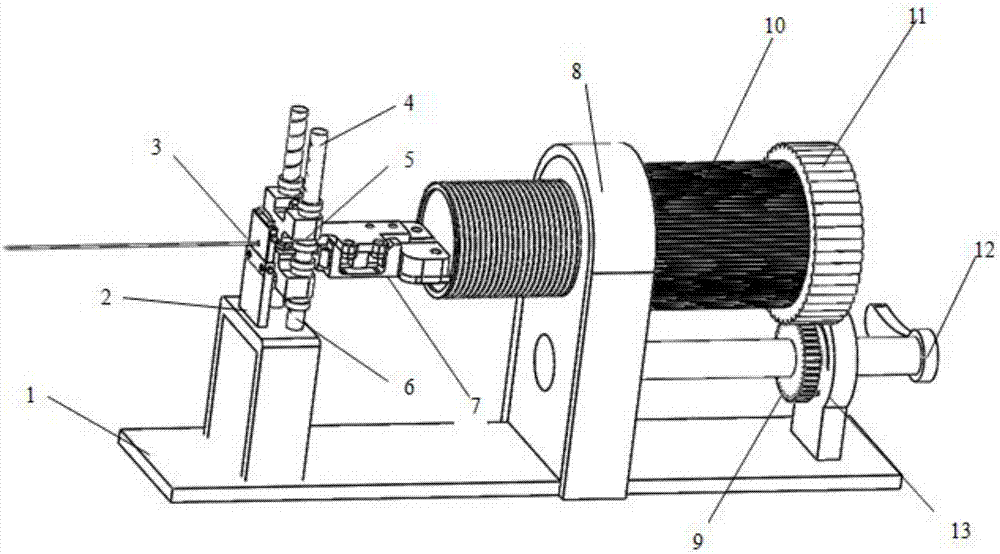
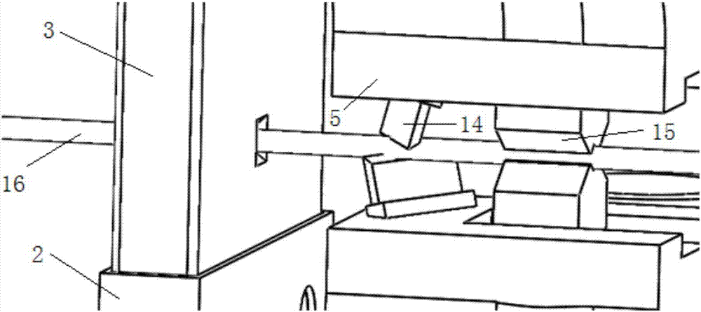
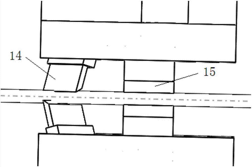
[0027] Such as figure 1 As shown, an optical fiber coating rotary stripping device provided by an embodiment of the present invention includes an optical fiber positioning and stripping unit and an optical fiber clamping and feeding unit, wherein the optical fiber positioning and stripping unit is used for positioning and stripping the optical fiber, The optical fiber clamping and feeding unit ...


PUM


Abstract

The invention discloses an optical fiber coating layer rotation stripping device. The optical fiber coating layer rotation stripping device comprises an optical fiber positioning stripping unit and an optical fiber clamping feeding unit; the optical fiber positioning stripping device comprises a stripping assembly and a positioning assembly; the stripping assembly comprises a pair of blades which are arranged vertically and are inclined relative to a horizontal plane, and the cutting edges of the blades are in different planes; the positioning assembly comprises a pair of positioning clamping blocks which are arranged vertically and are detachable; a distance between the cutting edge of a corresponding blade and an axis can be controlled through the positioning clamping blocks which clamp and position the optical fiber so as to control a cutting depth of the cutting edge; the optical fiber cutting unit comprises an optical clamp and a driving assembly; the optical clamp drives the optical fiber to rotate to feed under the driving of the driving assembly in order to produce a stripping force which is perpendicular to the cutting direction of the blade to realize stripping of the optical fiber coating layer. The optical fiber coating layer rotation stripping device can fast and effectively strip the optical fiber coating layer, and the stripped optical fiber has a good end surface and the internal cladding is not damaged.

Description

technical field [0001] The invention belongs to the field of optical fiber processing, and more specifically relates to an optical fiber coating layer rotary stripping device. Background technique [0002] With the continuous progress and development of optical fiber technology, optical fiber has been widely used in communication, sensing, processing, etc. As an advanced technology, fiber lasers, especially high-power lasers, will play a huge role in promoting important industries such as industry and national defense. Therefore, the research and development of high-power lasers has become a national key project in recent years. [0003] The preparation of fiber lasers involves related processing of optical fibers. In the process of processing optical fibers, the step usually required is to strip the outer coating layer of optical fibers, and the effect of stripping directly affects the quality and characteristics of optical fibers. . At present, there are many ways to str...

Claims


Application Information

Patent Timeline
Patent Type & Authority Applications(China)
IPC IPC(8): G02B6/245
CPCG02B6/245
Inventor 马修泉邵新宇青宸
Owner HUAZHONG UNIV OF SCI & TECH
Why Eureka
Eureka Blog
Learn More