
Full-automatic and efficient cleaned aluminum electrolysis cell

An aluminum electrolytic cell and fully automatic technology, which is applied in the field of aluminum electrolysis system, can solve the problems of shortening the pole changing time and achieve the effects of shortening the pole changing time, fast unmanned operation, and solving the uneven distribution of alumina concentration

Active Publication Date: 2017-08-18
CENT SOUTH UNIV +1
View PDF7 Cites 6 Cited by
  • Summary
  • Abstract
  • Description
  • Claims
  • Application Information

AI Technical Summary

Problems solved by technology

[0010] The technical problem solved by the present invention is to provide a new type of fully automatic, high-efficiency and clean aluminum electrolysis system to eliminate the hindrance of the upper crust on the electrolysis process, so as to greatly shorten the replacement time At the same time, the flue gas temperature is significantly increased and the pollutants in the flue gas are enriched. On this basis, through the automatic control of the whole process of aluminum electrolysis, the high energy efficiency of the whole process of aluminum smelting is realized (energy utilization rate>70%, tons of aluminum Energy consumption <10000kWh), ultra-low emissions (main pollutant emissions reduced by more than 90%) and workshop staff reduction by more than 80%

Method used


Image

  • Full-automatic and efficient cleaned aluminum electrolysis cell
  • Full-automatic and efficient cleaned aluminum electrolysis cell
  • Full-automatic and efficient cleaned aluminum electrolysis cell

Examples


Embodiment

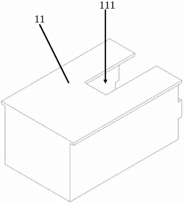
[0067] see Figure 1 to Figure 8 The controllable aluminum electrolytic cell anode covering sealing system in the illustration is a preferred solution arranged on the aluminum electrolytic cell of this embodiment, including a support frame 12 and several anode coating units 11 (in order to show the inside of the support frame structure, only represents one of the anode cladding units), wherein, the support frame 12 is a frame structure formed by welding several stainless steel rods and is installed above the aluminum electrolytic cell, and the side of the support frame 12 is connected with the groove of the aluminum-aluminum electrolytic cell The sides of the shell are sealed and fixed by side baffles. The top of the support frame 12 is welded by several parallel distributed stainless steel rods. The anode carbon blocks 8 are distributed between the gaps at the top of the support frame 12. The connected anode guide rods 81 Protruding from the gap between the supporting frame 1...


PUM


Abstract

The invention discloses a full-automatic and efficient cleaned aluminum electrolysis cell. The full-automatic and efficient cleaned aluminum electrolysis cell comprises an anode coverage sealing system arranged on a cell shell of the aluminum electrolysis cell, and meanwhile, cooperatively develops a full-automatic aluminum exchange, pole exchange and smoke afterheat recovery system to realize great recovery of lost heat in smoke and efficient centralized treatment of pollutants, so that the operation effects of ultralow electric consumption and ultralow emission are achieved, meanwhile, the workshop staff demands are greatly reduced, the contradiction between huge energy carried by the smoke and shorted smoke recovery methods (low temperature), the contradiction between huge total quantity of the pollutants and difficult treatment of the pollutants due to low concentration, and the contradiction between a lot of manual operations in bad environment and shorted automatic methods are solved, the enrichment of high-temperature smoke and the efficient recovery of the smoke energy in the electrolysis process are realized, the enrichment and the centralized treatment of the pollutants in the smoke are realized at the same time, and finally, the ultrahigh energy efficiency( the energy utilization rate is higher than 70%, and the tonnage aluminum energy consumption is lower than 10000 kWh), the ultralow emission ( the emission of main pollutants (such as PFC) is reduced by above 90%) and the full automation (the workshop staff is reduced by above 80%) in the whole aluminum smelting process can be realized.

Description

technical field [0001] The invention belongs to an aluminum electrolysis cell, and in particular relates to a fully automatic, efficient and clean aluminum electrolysis system. Background technique [0002] In 1886, American Hall and Frenchman Héroult independently invented the cryolite-alumina molten salt electrolytic aluminum smelting method, that is, the Hall-Héroult aluminum smelting method, which opened the prelude to the modern aluminum electrolysis industry. 2 o 3 Particles are used as raw materials, using Na 3 AlF 6 Molten salt is used as electrolyte, and carbon material is used as anode and cathode. Under the action of direct current, metal aluminum is obtained by electrolysis at a high temperature of 950°C. [0003] The Hall-Héroult aluminum smelting method is the only method for industrial production of metal aluminum so far. The current industrial aluminum electrolysis process has successively experienced small prebaking tanks, side conductive self-baking tank...

Claims


Application Information

Patent Timeline
IPC IPC(8): C25C3/12C25C3/20C25C3/22
CPCC25C3/12C25C3/20C25C3/22
Inventor 张红亮李劼丁凤其邹忠肖胜华
Owner CENT SOUTH UNIV
Learn More