Plant protection unmanned aerial vehicle
A technology for planting and protecting drones and arms, applied in the field of drones, can solve problems such as troublesome replacement of drone arms, and achieve the effect of convenient maintenance and replacement, quick disassembly and installation, and improved work efficiency
- Summary
- Abstract
- Description
- Claims
- Application Information
AI Technical Summary
Problems solved by technology
Method used
Image

Examples
Embodiment 1
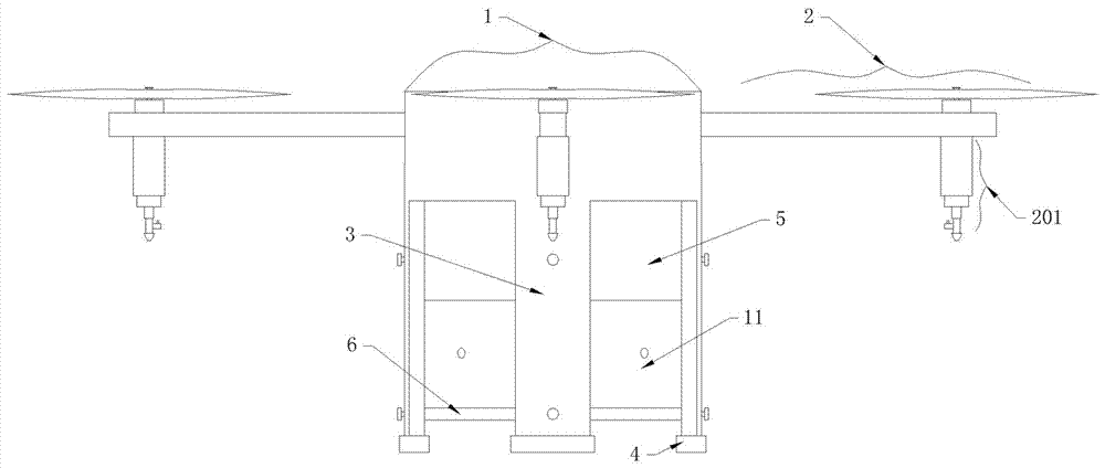
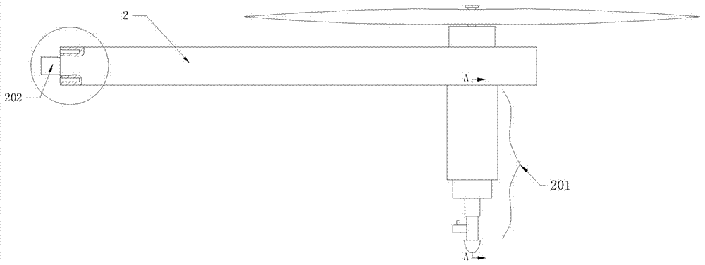
[0042] Embodiment one, such as Figure 1-9 , 13, 16 and 17, a drone for plant protection, including a center plate 1, an arm 2 connected to the side of the center plate 1 and a medicine box 5 connected to the bottom of the center plate 1, the center plate 1 and the medicine box The boxes 5 are all cylindrical structures, and several rectangular planes are cut out on the side of the central plate 1, and the left end of the machine arm 2 is detachably connected to the rectangular plane of the central plate 1, and the right side of the machine arm 2 The position close to the right end surface is provided with a rotor at the top and a retractable nozzle 201 at the bottom. The rectangular plane of the center plate 1 protrudes outwards with a board 101 , and the center board 1 is also provided with a And a recessed rectangular socket 103, the left end of the machine arm 2 is provided with a rectangular plug 202 extending to the left, the plug 202 is matched with the socket 103, and ...
Embodiment 2
[0043] Embodiment two, such as Figure 1-9 , 13, 16 and 17 are basically the same as the first embodiment. Preferably, several raised metal contacts 2021 are arranged above the plug 202, and the metal contacts 2021 are connected to the rotor through wires. The socket The inner wall of 103 is attached with a metal dome 1031 connected to the internal power supply, the top of the metal dome 1031 is provided with a contact groove for matching with the metal contact 2021, the metal contact 2021 is a cuboid structure, and the plug 202 is provided with It leads to the communication hole 2022 inside the machine arm 2 .
[0044] When installing the machine arm 2, insert the plug 202 on the machine arm 2 into the socket 103 on the center plate 1, and at the same time insert the plug plate 101 on the center plate 1 into the slot I 104 on the machine arm 2, and insert the pin 102 on the center plate 1 The socket 204 on the machine arm 2, the upper screw hole 205 and the lower screw hole ...
Embodiment 3
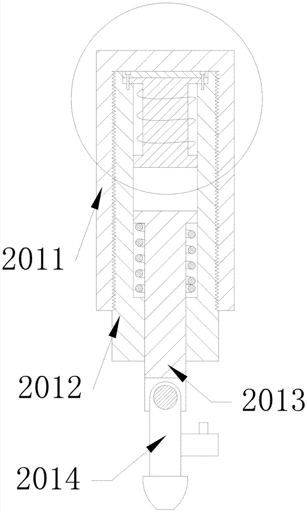
[0045] Embodiment three, such as Figure 1-9 , 13, 16 and 17 are basically the same as the second embodiment. Preferably, the inner wall of the telescopic tube 2012 is provided with an annular notch located at the upper end and communicated with the cavity, and the upper end of the electromagnet 2015 is provided with an annular notch located in the annular notch. The upper end of the electromagnet 2015 is provided with a cover plate 2016, the cover plate 2016 and the annular edge are fixed on the telescopic tube 2012 by countersunk screws, and the magnetic column 2013 is covered with a cover located under the baffle plate and located on the telescopic The spring in the cavity of the barrel 2012 prevents the magnetic column 2013 from falling sharply and damages the nozzle 2014.
[0046] The working process of the nozzle: when the electromagnet 2015 is energized in the forward direction, the polarity of the electromagnet 2015 and the magnetic column 2013 are opposite, and the ma...
PUM
 Abstract
Description
Claims
Application Information
 - R&D
- Intellectual Property
- Life Sciences
- Materials
- Tech Scout
- Unparalleled Data Quality
- Higher Quality Content
- 60% Fewer Hallucinations
Browse by: Latest US Patents, China's latest patents, Technical Efficacy Thesaurus, Application Domain, Technology Topic, Popular Technical Reports.
© 2025 PatSnap. All rights reserved.Legal|Privacy policy|Modern Slavery Act Transparency Statement|Sitemap|About US| Contact US: help@patsnap.com