
Mechanism capable of realizing two times of core pulling and forcible hole stripping operation by virtue of slide

A technology of slider 2 and slider, which is applied in the field of slider secondary core-pulling and strong hole removal mechanism, can solve problems such as the overall structure of the mold, and achieve the effects of reducing the configuration of the mold mechanism, reducing the volume of the mold, and simplifying the structure of the mold

Pending Publication Date: 2017-08-18
SHENTONG TECH GRP CO LTD
View PDF3 Cites 5 Cited by
  • Summary
  • Abstract
  • Description
  • Claims
  • Application Information

AI Technical Summary

Problems solved by technology

But what this utility model solves is the technical problem of the demoulding of the undercut column with the outer undercut structure. This utility model cannot solve the mold removal problem of the U-shaped buckle with the inner undercut structure, and this utility model can only complete the first step. The separation action of the insert and the second insert provides conditions for the demoulding of the fixed column on the injection molded product, but the final demoulding of the product needs to be completed by other mechanisms, and the overall structure of the mold is relatively complicated

Method used


Image

  • Mechanism capable of realizing two times of core pulling and forcible hole stripping operation by virtue of slide
  • Mechanism capable of realizing two times of core pulling and forcible hole stripping operation by virtue of slide
  • Mechanism capable of realizing two times of core pulling and forcible hole stripping operation by virtue of slide

Examples


Embodiment

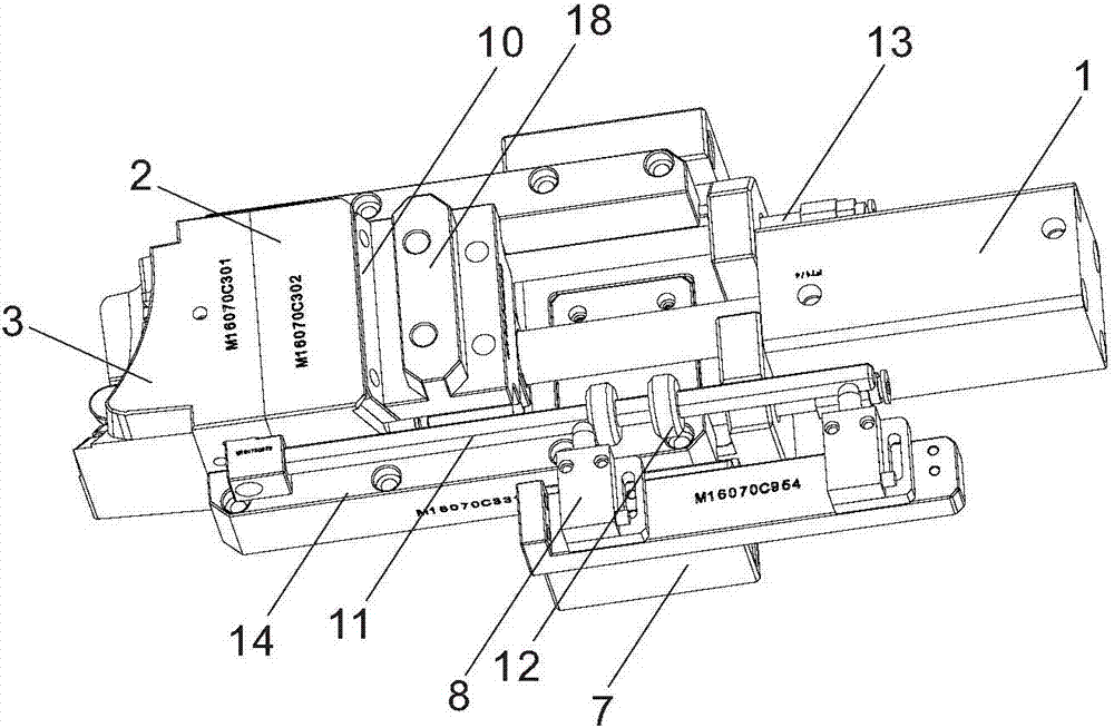
[0029] Such as Figure 1 to Figure 10As shown, a slider secondary core-pulling strong hole removal mechanism is set on the mold. The slider secondary core-pulling strong hole removal mechanism includes an oil cylinder 1, a slider body 2, a slider head 3, and a threaded limit sleeve 4. The outer pin 5 of the U-shaped buckle and the center pin 6 of the U-shaped buckle that can be extended to the mold core, the piston rod of the oil cylinder 1 is connected with the slider body 2, and the slider body 2 and the slider head 3 are slid and connected to each other. On a pair of parallel guide rods 13, the guide rods 13 are fixed on a base frame 7, so that the slider body 2 and the slider head 3 are slidably connected with the base frame 7. The outer pins 5 of the U-shaped buckle are fixed on the slider body 2 and slide through the slider head 3. The outer pins 5 of the U-shaped buckle are arranged in pairs, and there are two pairs in total. The central pin 6 of the U-shaped buckle is ...


PUM


Abstract

The invention discloses a mechanism capable of realizing two times of core pulling and forcible hole stripping operation by virtue of a slide. The mechanism is arranged on a mold and is characterized by comprising an oil cylinder, a slide body, a slide head, a threaded limiting sleeve, and U-shaped buckle lateral pins and a U-shaped buckle center pin which are capable of extending to a mold core of the mold, wherein a piston rod of the oil cylinder is connected to the slide body, the slide body and the slide head are slideably connected to a bottom frame, the U-shaped buckle lateral pins are fixedly arranged on the slide body and slideably penetrate through the slide head, and the U-shaped buckle center pin is fixedly arranged on the slide head; the U-shaped buckle center pin is provided with a protrusion part used for forming an inner undercut structure of an injection product; the threaded limiting sleeve is connected between the slide body and the slide head; a limited travel pull rod is slideably arranged inside the threaded limiting sleeve, and the end of the limited travel pull rod is fixed on the slide head; the slide head is provided with a U-shaped buckle forming hole leading to the mold core of the mold, and the U-shaped buckle center pin is arranged in the U-shaped buckle forming hole in a penetrating manner; and the bottom frame is fixedly provided with a travel switch used for detecting the moving travel of the slide head.

Description

technical field [0001] The invention relates to a mold working mechanism, more specifically, it relates to a sliding block secondary core-pulling and strong hole-removing mechanism. Background technique [0002] Many injection molding products have U-shaped buckles with inner undercut structures. The processing method of directly forming the inner undercut structure by melting the material is the most ideal. The inner undercut structure generated in this way is smooth and continuous, with good consistency, complete structure and high strength. High, but one of the biggest difficulties in implementing this processing method is that when the mold is opened, the step structure of the forming hole of the U-shaped buckle and the inner undercut structure on the mold has formed a bite with the cured rubber, and when the mold is opened, generally only a simple Move in a straight line, so the U-shaped buckle of the injection molded product cannot be separated from the forming hole on...

Claims


Application Information

Patent Timeline
IPC IPC(8): B29C45/33B29C45/44
CPCB29C45/33B29C45/4435B29C2045/445
Inventor 方立锋蔡炳芳项勇毛元源
Owner SHENTONG TECH GRP CO LTD
Learn More