Continuous-flow tubular reaction system and reaction control system

A tubular reaction and flow controller technology, which is applied in chemical/physical/physical chemical fixed reactors, control/regulation processes, chemical/physical/physical chemical processes, etc., can solve the problem of inability to achieve precise temperature control and online Monitoring, large footprint, mass transfer, heat transfer and mixing are not uniform enough to achieve the effect of low production cost, small volume and floor space, and increased length

Active Publication Date: 2017-08-18
山东省诺为流动化学研究院有限公司
View PDF4 Cites 4 Cited by
  • Summary
  • Abstract
  • Description
  • Claims
  • Application Information

AI Technical Summary

Problems solved by technology

[0004] The present invention proposes a continuous flow tubular reaction system and a reaction control system to solve the problem that the existing tubular reaction system occupies a large area, the mass transfer and heat transfer mixing are not uniform enough, and the precise temperature control and online monitoring cannot be achieved. question

Method used


Image

  • Continuous-flow tubular reaction system and reaction control system
  • Continuous-flow tubular reaction system and reaction control system
  • Continuous-flow tubular reaction system and reaction control system

Examples


Embodiment 1

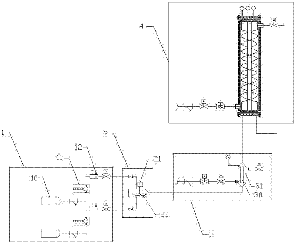
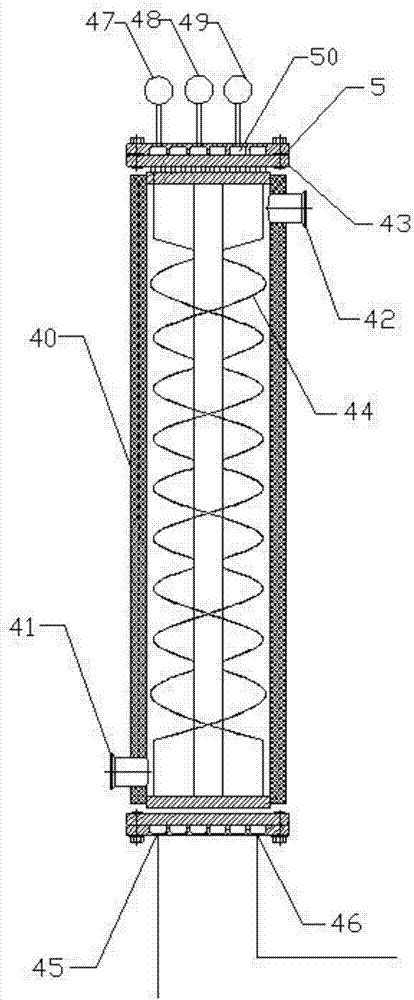
[0030] Such as Figure 1-2 As shown, the continuous flow tubular reaction system of this embodiment includes a feeding device 1 , a mixing device 2 , a preheating device 3 and a reaction device 4 connected in sequence.

[0031] Wherein, the feeding device 1 comprises a plurality of sequentially connected raw material tanks 10, feed pumps 11 and flow controllers 12, each raw material tank 10 is used to hold a reaction solution, and the flow controller 12 is used to control the feeding The pump 11 draws the reaction solution from the raw material tank 10 at a certain rate.

[0032] A stirring paddle 20 is installed in the mixing device 2, and the stirring paddle 20 is driven by a servo motor 21 for mixing the reaction solution extracted from the raw material tank 10 to obtain a mixed solution.

[0033] The preheating device 3 includes a preheating tube side 30 and a preheating shell side 31, the preheating tube side 30 is used for circulating the mixed solution introduced from ...

Embodiment 2

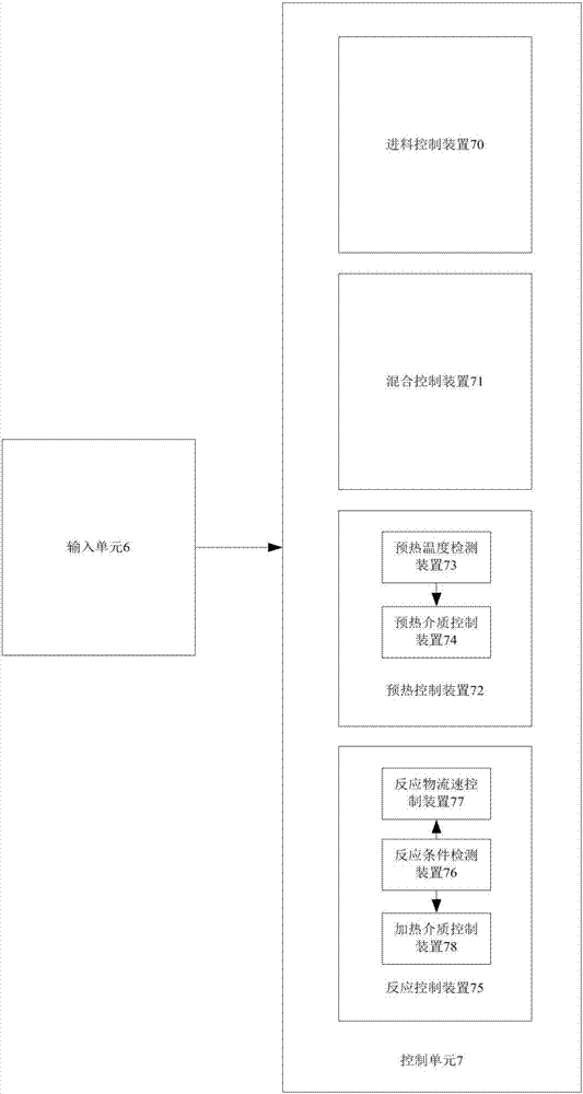
[0040] This embodiment discloses a continuous flow tube reaction control system, including an input unit 6 and a control unit 7, the input unit 6 is used to select a preset reaction mode, and the control unit 7 is selected based on the input unit 6 The reaction mode is used to output control signals to control the operation of the continuous flow tubular reaction system; wherein, the control unit 7 includes:

[0041] Multiple groups of feed control devices 70, each group of feed control devices 70 are connected to a raw material tank 10 for controlling the flow rate and flow rate of each reaction solution;

[0042] a mixing control device 71, configured to control the rotational speed of the servo motor 21;

[0043]The preheating control device 72 includes a preheating temperature detection device 73 and a preheating medium control device 74, the preheating temperature detection device 73 is used to detect the temperature of the preheating solution in the preheating tube 30 of...


PUM


Abstract

The invention relates to the technical field of chemical pharmacy, in particular to a continuous-flow tubular reaction system and a reaction control system. The reaction system includes a feeding device, a mixing device, a pre-heating device and a reaction device, wherein the feeding device, the mixing device, the pre-heating device and the reaction device are communicated in sequence; reaction tubes in the reaction device are communicated in sequence through communicating devices, and the reaction control system includes an input device used for selecting a preset reaction model and a control unit which used for outputting a control signal according to the selected reaction model and controlling normal operation of the continuous-flow tubular reaction system according to the reaction condition. According to the continuous-flow tubular reaction system and the reaction control system, the mixing effect is good, the reaction condition is controlled precisely, the reaction efficiency and the yield are improved, the size and the occupied space are relatively small, the production cost is reduced, the spirally wound reaction tubes are adopted, the mixing effect is good and the service life of equipment is long.

Description

technical field [0001] The invention relates to the technical field of chemical industry and pharmacy, in particular to a continuous flow tube reaction system and a reaction control system. Background technique [0002] Reactor equipment commonly used in the field of chemical and pharmaceutical technology includes tubular reactors and tank reactors, etc. Among them, tank reactors are often equipped with stirring devices in the reactor for mixing liquid phase reactants. The conversion rate is low, and the energy consumption and pollution are serious. Due to the high requirements for the purity of products in the chemical and pharmaceutical fields, the commonly used reactor equipment is a continuous flow tube reactor. [0003] The concentration and reaction rate of chemical reactants in the tubular reactor change with the length of the tube, so the tubular reactor needs to meet the tube length required by the chemical reaction, and the existing straight tube reactor or U-shap...

Claims


Application Information

Patent Timeline
IPC IPC(8): B01J19/24
CPCB01J19/0006B01J19/0013B01J19/242B01J19/243B01J2219/0006B01J2219/00164B01J2219/00189B01J2219/2409B01J2219/2418B01J2219/2422
Inventor 陈延坤
Owner 山东省诺为流动化学研究院有限公司
Why Eureka
Try Eureka