
Composite hydrogen resisting permeating layer on surface of metal hydride and preparation method thereof

A technology of surface compounding and hydride, which is applied in the direction of metal material coating process, coating, liquid chemical plating, etc., can solve the problems of easy generation of microcracks, interlayer defects, and loose interlayer bonding, etc., to achieve enhanced resistance Hydrogen permeability, no obvious cracks, tight combination effect

Active Publication Date: 2017-08-15
有研资源环境技术研究院(北京)有限公司
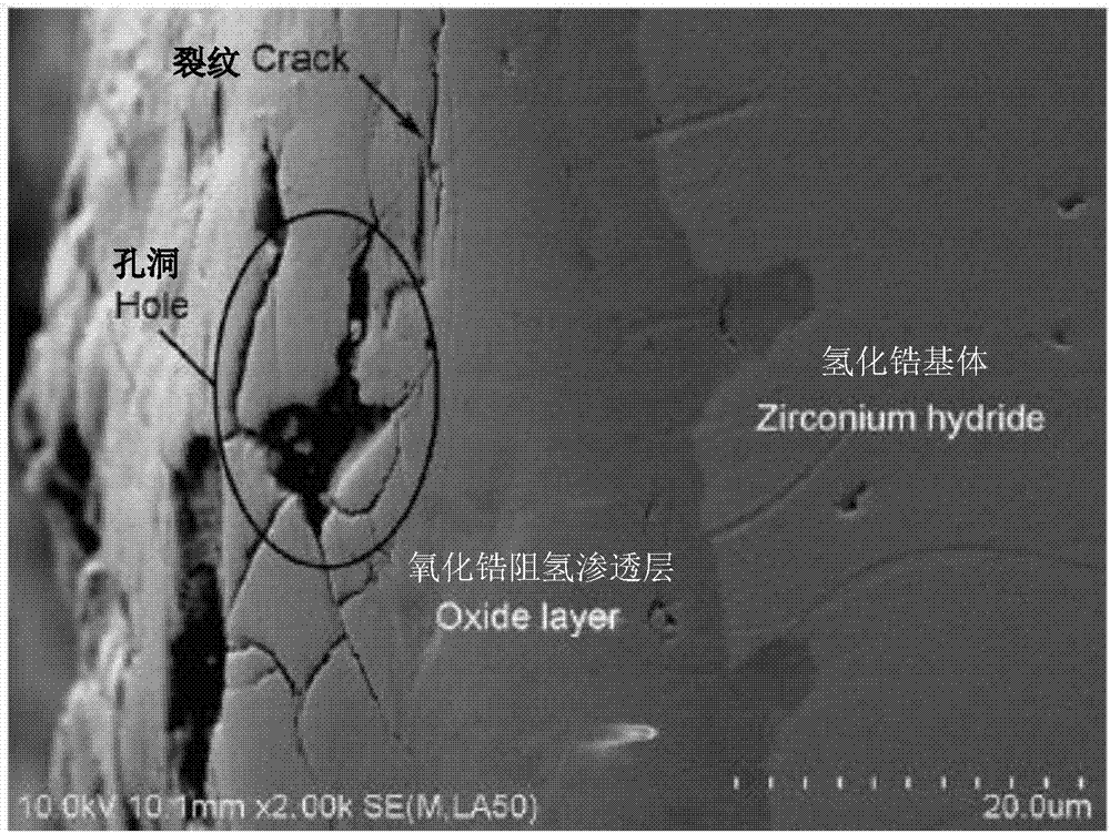
View PDF4 Cites 6 Cited by
  • Summary
  • Abstract
  • Description
  • Claims
  • Application Information

AI Technical Summary

Problems solved by technology

However, the above-mentioned film layer is mainly covered on the surface of the substrate, and there are problems such as interlayer defects and loose interlayer bonding, which are easy to peel off
[0005] In addition, when preparing a hydrogen barrier layer on the surface of metal hydrides such as zirconium hydride, it is necessary to consider that the hydride matrix is ​​highly brittle and prone to microcracks, the process of preparing the hydrogen barrier layer prevents hydrogen loss, and the preparation method is suitable for the use requirements of structura

Method used


Image

  • Composite hydrogen resisting permeating layer on surface of metal hydride and preparation method thereof
  • Composite hydrogen resisting permeating layer on surface of metal hydride and preparation method thereof
  • Composite hydrogen resisting permeating layer on surface of metal hydride and preparation method thereof

Examples


Example Embodiment

[0033] Example 1

[0034] (1) The edge of the metal zirconium hydride substrate with Φ20mm×20mm and H / Zr atomic ratio of 1.85 is chamfered at an angle of 45°, the chamfer radius is 1.5mm, the surface is polished, and then dried with acetone ultrasonic cleaning. Coating organosilica sol coating on the surface of zirconium hydride by dipping and pulling method to control the coating thickness to be about 1 μm. The temperature is increased to 50°C, 120°C, 180°C, 250°C at a temperature rising rate of 300°C / h, and the temperature is kept at 50°C, 120°C, 180°C, and 250°C for 100 hours, and then the sample is cooled to a temperature of 100°C / h Room temperature.

[0035] (2) Seal the zirconium hydride substrate with dry organosilica sol coating in a stainless steel reaction vessel with vacuum tube and vent tube, place the reaction vessel in a temperature-controlled tubular heating furnace, and vacuum the reaction vessel to 3.0 ×10 -4 Pa; After that, 5%, 15%, 80% of CO and CO are introduc...

Example Embodiment

[0038] Example 2

[0039] (1) The edge of the zirconium hydride substrate with Φ30mm×40mm and the H / Zr atomic ratio of 2.0 is chamfered to an angle of 45°, the chamfering radius is 2mm, the surface is polished, and then dried by ultrasonic cleaning with acetone. The surface of zirconium hydride is coated with an organic silica sol coating modified by nano-alumina sol by dipping and pulling method, and the coating thickness is controlled to be about 2 μm. The temperature was increased to 120°C and 200°C at a heating rate of 50°C / h, and the temperature was kept constant at 120°C and 200°C for 1 hour, and then the sample was cooled to room temperature at a temperature drop of 300°C / h.

[0040] (2) Seal the zirconium hydride substrate with dry organosilica sol coating in a quartz reaction vessel with a vacuum tube and a vent tube, place the reaction vessel in a temperature-controlled heating furnace, and vacuum the reaction vessel until it reaches 1×10 -5 Pa; After that, CO and CO of ...

Example Embodiment

[0041] Example 3

[0042] (1) The edge of the hafnium hydride substrate with Φ20mm×50mm and the H / Hf atomic ratio of 1.75 is chamfered at an angle of 45°, the surface is polished, and then dried by ultrasonic cleaning with acetone. An organic silica sol coating modified by nano-oxidized bait sol is plated on the surface of hafnium hydride by dipping and pulling method, and the thickness of the coating is controlled to be about 3 μm. The temperature was increased to 50°C, 120°C, and 180°C at a temperature increase rate of 300°C / h, and the temperature was kept at 50°C, 120°C, and 180°C for 30 hours. Then the sample was cooled to room temperature at a temperature drop rate of 50°C / h.

[0043] (2) Seal the hafnium hydride substrate with the dried organosilica sol coating in a heat-resistant glass reaction vessel with a vacuum tube and a vent tube, place the reaction vessel in a temperature-controlled heating furnace, and vacuum the reaction vessel until it is evacuated. Vacuum to 100P...


PUM

PropertyMeasurementUnit
Thicknessaaaaaaaaaa
Thicknessaaaaaaaaaa
Thicknessaaaaaaaaaa

Abstract

The invention relates to a composite hydrogen resisting permeating layer on the surface of metal hydride and a preparation method thereof. The preparation method comprises the steps that through the dipping-pulling method, an organic silica solution or a mingled and modified organic silica solution coating is prepared on the surface of the metal hydride, or a modified organic silica solution coating is mingled on the surface of the metal hydride; after being subjected to segmental constant-temperature drying at 50-250 DEG C, a metal hydride matrix coated with the organic silica solution coating is sealed into a reacting container provided with a vacuumizing pipe and a breather pipe, the reacting container is arranged in a temperature-controlling heating furnace in a sealed mode, mixed gas containing carbon oxygen, nitrogen oxygen or carbon-nitrogen oxygen are introduced, and segmental constant-temperature sintering is conducted at 300-850 DEG C; after temperature-controlling cooling or furnace cooling, the composite hydrogen resisting permeating layer composed of the outer layer of an organic silica solution sintering layer and the inner layer of an in-situ reacting layer containing the carbon oxygen, the nitrogen oxygen or the carbon-nitrogen oxygen is prepared on the surface of the metal hydride matrix. The composite hydrogen resisting permeating layer is compact and continuous and tightly combined with the metal hydride matrix and has a hydrogen resisting permeating effect on the metal hydride matrix.

Description

technical field [0001] The invention belongs to the technical field of metal hydride surface hydrogen permeable layer, in particular to a metal hydride surface composite hydrogen permeable layer and a preparation method thereof. Background technique [0002] Metal hydride has the function of storing and fixing hydrogen, and is often used as a hydrogen storage material. However, at a certain temperature, hydrogen will be released from the metal hydride due to thermodynamic equilibrium, thereby reducing the hydrogen content of the metal hydride and ensuring that the hydrogen content does not decrease. Or to make the reduction rate very low, a common method is to prepare a hydrogen permeable barrier coating on the metal hydride surface. [0003] The currently reported hydrogen permeable ceramic materials mainly include oxides, carbides and other metal-based ceramic materials; the common oxide materials are Al 2 o 3 、Cr 2 o 3 , ZrO 2 、Er 2 o 3 , SiO 2 , Y 2 o 3 etc.; c...

Claims


Application Information

Patent Timeline
IPC IPC(8): C23C8/28C23C8/02C23C18/12
CPCC23C8/02C23C8/28C23C18/1208C23C18/1245C23C18/1254
Inventor 王力军陈洋吴明张顺利张建东闫国庆彭家庆
Owner 有研资源环境技术研究院(北京)有限公司
Learn More