
Equipment for automatically pressing decorative ring of automobile instrument

A technology for automotive instruments and decorative rings, applied in metal processing equipment, vehicle parts, transportation and packaging, etc., can solve the problems of low assembly pass rate, high assembly difficulty, low work efficiency, etc., achieve convenient operation, save assembly time, The effect of simple structure

Inactive Publication Date: 2017-08-15
AEROSPACE HI TECH HLDG GROUP
View PDF14 Cites 4 Cited by
  • Summary
  • Abstract
  • Description
  • Claims
  • Application Information

AI Technical Summary

Problems solved by technology

[0004] The purpose of the present invention is to solve the problems of high assembly difficulty, easy damage, low assembly pass rate, low work efficiency and high cost in the assembly process of existing automotive instrument trim rings
Furthermore, an automatic press-fitting decoration ring equipment for automobile instrument is provided

Method used


Image

  • Equipment for automatically pressing decorative ring of automobile instrument
  • Equipment for automatically pressing decorative ring of automobile instrument
  • Equipment for automatically pressing decorative ring of automobile instrument

Examples


specific Embodiment approach 1

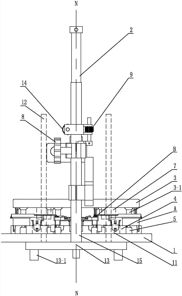
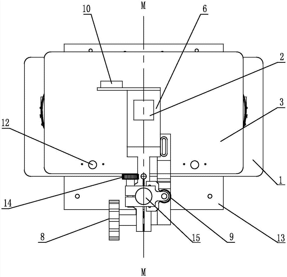
[0023] Specific implementation mode one: combine Figure 1 to Figure 4 Describe this embodiment, a device for automatically pressing a decorative ring for an automobile instrument in this embodiment, which includes a base plate 1, a cylinder 2, an upper pressing plate 3, a slide plate 6, a slide plate knob 8, a pneumatic knob 10, a seat plate 13, and a support column 15 , two support limit blocks 4, two linear bearings 7, two optical axes 12 and a plurality of pallets 5, the upper platen 3, the bottom plate 1 and the seat plate 13 are all rectangular plates, the upper platen 3, the base plate 1 and the seat plate 13 is arranged in sequence from top to bottom along the N-N direction of the longitudinal axis of the cylinder 2, the seat plate 13 is placed horizontally, the bottom plate 1 is fixed on the seat plate 13, the two support limit blocks 4 are cylindrical limit blocks, and the two cylindrical limit blocks The positioning blocks 4 are symmetrically arranged on the upper e...

specific Embodiment approach 2

[0024] Specific implementation mode two: combination figure 1 This embodiment will be described. The lower end of the seat plate 13 in this embodiment is provided with a plurality of bosses 13-1. Such setting ensures the stability of the seat plate 13, so that the seat plate 13 can be placed on the worktable smoothly. Other compositions and connections are the same as in the first embodiment.

specific Embodiment approach 3

[0025] Specific implementation mode three: combination figure 1 The present embodiment will be described. The heights of the plurality of trays 5 in this embodiment are equal to the heights of the two support stoppers 4 . Such an arrangement ensures the flatness of the workpiece A on the plurality of pallets 5 and the two supporting limit blocks 4 . Other compositions and connections are the same as those in Embodiment 1 or Embodiment 2.


PUM


Abstract

The invention discloses equipment for automatically pressing a decorative ring of an automobile instrument, and relates to the technical field of automobile instrument equipment. The equipment aims to solve the problems such as difficult assembly difficulty, easy damage, a low assembly qualification rate, low working efficiency and high manufacturing cost in an assembly process of an existing automobile instrument decorative ring. Two supporting limiting blocks are arranged on the upper end surface of a bottom plate; a plurality of trays are arranged around the supporting limiting blocks; the lower ends of the trays are fixedly connected to the upper end of the bottom plate; ends of two optical shafts pass through the bottom plate, and are fixedly arranged at the upper end of the bottom plate through two pin bases; the other ends of the two optical shafts pass through an upper pressure plate and are fixedly connected to the lower end of the upper pressure plate through two linear bearings; the lower end of an air cylinder is vertically and fixedly connected on the center at the upper end of the upper pressure plate; one end of a slide plate is in movable sleeve connection on the lower part of the air cylinder; the other end of the slide plate is in movable sleeve connection on the upper end of a supporting post; and the middle part of the slide plate is connected with the upper end of the upper pressure plate through a connecting plate. The equipment is used for assembling the decorative ring on the automobile instrument.

Description

technical field [0001] The invention relates to the technical field of automobile instrumentation equipment, in particular to an automatic press-fitting decoration ring equipment for automobile instrumentation. Background technique [0002] Automobile instrument is composed of mechanical structure, software control, and printed circuit board. The mechanical structure accounts for more than 80% of the overall parts. The decorative ring is an important station in the overall instrument assembly process. The assembly process is complicated. It is easy to be damaged, and long-term manual assembly is prone to personnel fatigue, poor assembly effect, resulting in a lower product qualification rate, resulting in a large waste of resources and economic waste. [0003] To sum up, the existing automotive instrument bezels have the problems of high assembly difficulty, easy damage, low assembly pass rate, low work efficiency and high cost in the assembly process. Contents of the inve...

Claims


Application Information

Patent Timeline
Patent Type & Authority Applications(China)
IPC IPC(8): B23P19/027
CPCB23P19/027B23P2700/50
Inventor 何琳张志波韩浩刘明月查森懿
Owner AEROSPACE HI TECH HLDG GROUP
Learn More