A reflective surface for deployable antenna supported by rib mesh and its design method

A reflective surface and antenna technology, applied to antennas, electrical components, etc., can solve the problems of low folding efficiency, unstable shape, and high launch cost of solid-surface antennas, and achieve simple and fast induction methods, improve shape accuracy, and wide applicability Effect

Active Publication Date: 2020-11-24
HARBIN INST OF TECH
View PDF2 Cites 0 Cited by
  • Summary
  • Abstract
  • Description
  • Claims
  • Application Information

AI Technical Summary

Problems solved by technology

[0003] In order to solve the deficiencies of low rigidity and unstable shape of the reflective surface of the thin-film space expansion antenna, which lead to low precision of the surface shape, as well as the low folding efficiency of the solid-surface antenna and the high launch cost, the present invention provides a rigid-flexible intelligent The reflective surface and design method of rib-mesh support deployable antenna with variable configuration realized by conversion

Method used


Image

  • A reflective surface for deployable antenna supported by rib mesh and its design method
  • A reflective surface for deployable antenna supported by rib mesh and its design method
  • A reflective surface for deployable antenna supported by rib mesh and its design method

Examples


specific Embodiment approach 1

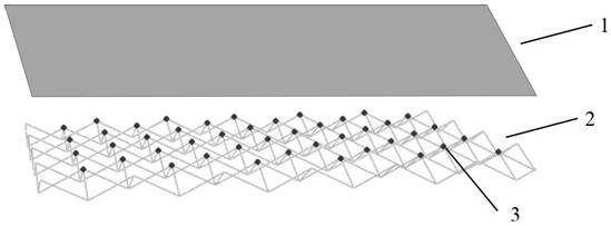
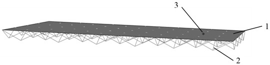
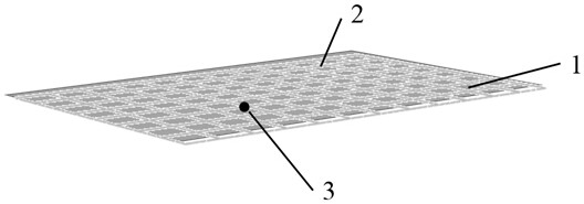
[0023] Specific implementation manner one: such as Figure 1-4 As shown, the rib-net-supported expandable antenna reflective surface provided by this embodiment through rigid-flexible intelligent conversion to achieve a variable configuration is composed of a reflective surface layer 1 and a rib network structure layer 2. The network node 3 is fixedly connected to the reflecting surface layer 1. The reflecting surface layer 1 provides the physical functions required by the antenna reflecting surface, and the rib network structure layer 2 provides spatial support for the reflecting surface layer 1, maintaining the structural shape of the reflecting surface and ensuring the antenna reflecting surface The structural stability and shape accuracy of the

[0024] In this embodiment, the deformed configuration of the reflective surface of the fin-supported deployable antenna is realized through the intelligent conversion of rigid and flexible. The initial state of the reflective surface...

specific Embodiment approach 2

[0031] Embodiment 2: This embodiment is different from Embodiment 1 in that the material selected for the rib network structure layer is one or more of shape memory alloy, shape memory polymer, and shape memory composite material.

specific Embodiment approach 3

[0032] Specific embodiment three: this embodiment is different from specific embodiments one and two in that the structure of the reflection surface of the deployed antenna is a plane, a parabola or a cylinder.


PUM


Abstract

The invention discloses a rib-network-supporting expandable antenna reflecting surface based on rigid-and-flexible intelligent conversion for variable configuration realization and a design method thereof. The rib-network-supporting expandable antenna reflecting surface comprises a reflection surface layer and a rib network structure layer; and a network node of the rib network structure layer is fixedly connected with the reflection surface layer. The variable configuration of the rib-network-supporting expandable antenna reflecting surface is realized by rigid-and-flexible intelligent conversion. The initial state of the rib-network-supporting expandable antenna reflecting surface is a moulded 3D stereo spatial rib network structure. When the antenna reflecting surface is used in a ground state, the 3D stereo spatial rib network structure in transformed into a two-dimensional reflecting surface by intelligent induction; after folded packaging, emission, and injection, the two-dimensional reflecting surface is transformed into a 3D stereo state by intelligent induction and solidification and sizing are carried out, so that the reflecting surface with a stable structural shape works in space in a high rigid manner. According to the variable-configuration antenna reflecting surface, a repeated folding and expanding function can be realized in a 2D state and a high rigidity function can be realized in a 3D state.

Description

Technical field [0001] The invention relates to a rib-net-supported expandable antenna reflecting surface with variable configuration realized through rigid-flexible intelligent conversion and a design method thereof, realizing repeated folding of the antenna reflecting surface on the ground, and converting the configuration into a high-rigidity form after launching into orbit, and expanding the antenna to space The application has a propelling effect. Background technique [0002] With the development of aerospace science and technology, the development of large-caliber, high-precision, light-weight expandable antennas is the development trend of space-expandable antennas. During the launch process, it is in a folded and stored (closed) state. After launching into orbit, it will be commanded by the ground The central control structure is gradually unfolded according to the design requirements to become a large space structure, and then locked and kept in operational working cond...

Claims


Application Information

Patent Timeline
Patent Type & Authority Patents(China)
IPC IPC(8): H01Q15/14
CPCH01Q15/14H01Q15/141
Inventor 王长国谭惠丰陶强王亚飞赵字会
Owner HARBIN INST OF TECH
Why Eureka
Try Eureka