
Frictional wear testing machine for hard alloy or wear-resistant coating and frictional wear testing method

A friction and wear test and wear-resistant coating technology, applied in the field of friction and wear, can solve the problems of high manufacturing cost, large space occupation, long detection time, etc., and achieve the effect of short test time, low cost and simple structure

Active Publication Date: 2017-08-11
HEFEI UNIV OF TECH
View PDF9 Cites 13 Cited by
  • Summary
  • Abstract
  • Description
  • Claims
  • Application Information

AI Technical Summary

Problems solved by technology

Due to the many shortcomings of these testing machines in terms of high manufacturing cost, long detection time, large space occupation, and low loading, some testing machines can only achieve single-parameter (fixed speed, low load) control, which has not adapted to the requirements of the development of the times.

Method used


Image

  • Frictional wear testing machine for hard alloy or wear-resistant coating and frictional wear testing method
  • Frictional wear testing machine for hard alloy or wear-resistant coating and frictional wear testing method
  • Frictional wear testing machine for hard alloy or wear-resistant coating and frictional wear testing method

Examples


specific Embodiment approach

[0034] It should be noted that the structures, proportions, sizes, etc. shown in the drawings attached to this specification are only used to match the content disclosed in the specification, for those who are familiar with this technology to understand and read, and are not used to limit the implementation of the present invention Any modification of the structure, change of the proportional relationship or adjustment of the size shall still fall within the scope of the technical content disclosed in the present invention without affecting the effect and the purpose of the present invention. within the scope covered.

[0035] At the same time, terms such as "upper", "lower", "left", "right", "middle" and "one" quoted in this specification are only for the convenience of description and are not used to limit this specification. The practicable scope of the invention and the change or adjustment of its relative relationship shall also be regarded as the practicable scope of the...

Embodiment 1

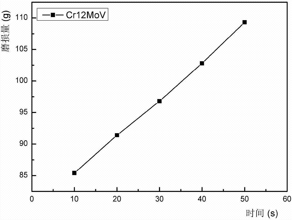
[0047] Select Cr 12 MoV is used as the sample to be tested, and the diamond grinding disc is used for grinding to speed up the experimental process. The friction and wear test method for cemented carbide or wear-resistant coating is as follows:

[0048] Step 1: Weigh the initial mass m of the sample to be tested with an electronic balance 0 5114.4 mg;

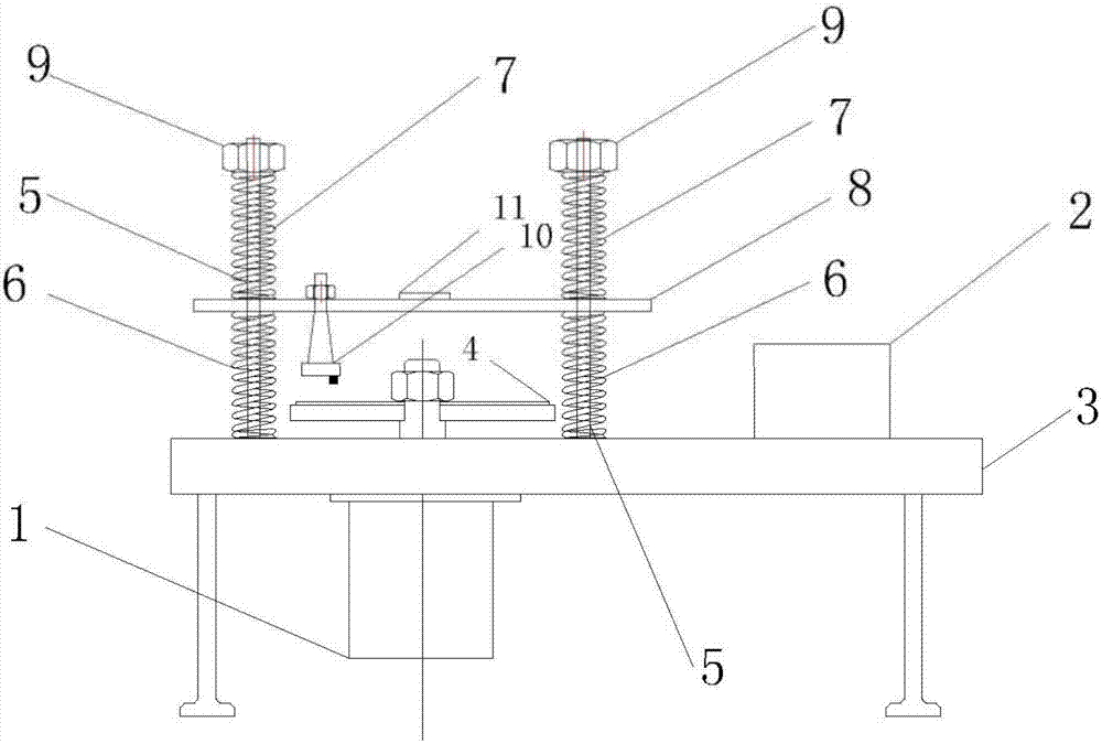
[0049] Step 2: Clamp the sample to be tested to the fixture of the friction and wear testing machine, and adjust the length of the support spring and the loading spring through the adjustment nut to make the upper splint level. At this time, the sample to be tested cannot be in contact with the abrasive tool; adjust the frequency conversion Reduce the rotation frequency of the grinding disc to 100-200 rpm, slowly adjust the adjusting nut, compress the spring, keep the upper splint horizontal during the adjustment process, until the sample to be tested is in contact with the grinding disc, turn off the switch, the state at thi...


PUM


Abstract

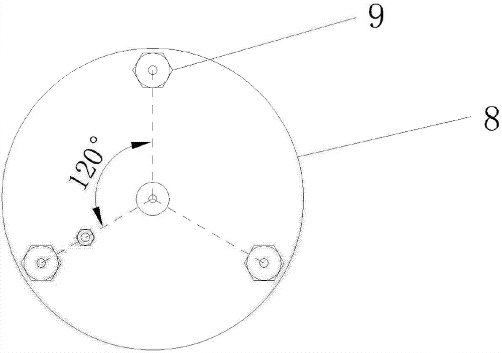
The invention discloses a frictional wear testing machine for a hard alloy or a wear-resistant coating and a frictional wear testing method. The frictional wear testing machine comprises a motor, a frequency converter, a rack and an abrasive disc, wherein the motor is mounted below the rack and connected with the frequency converter; the abrasive disc is fixedly connected onto an output shaft of the motor in a sleeving manner by virtue of a screw hole in the center of a circle; moreover, a plurality of screw supporting arms are vertically arranged on the rack, supporting springs are mounted at the lower parts of the screw supporting arms in a sleeving manner, and loading springs are mounted at the upper parts of the screw supporting arms in a sleeving manner; and an upper clamping plate is horizontally arranged above the rack, fixedly clamped through the supporting springs and the loading springs and is used for adjusting the level and load through adjusting nuts at the tops of the screw supporting arms. The device disclosed by the invention can be used for adjusting the pressure by changing the elongation of each loading spring, and is simple in structure, low in construction cost, suitable for a frictional wear test on the hard alloy or the surface wear-resistant coating, short in experimental time and saved in time and labor.

Description

[0001] 1. Technical field [0002] The invention relates to a friction and wear testing machine and a friction and wear testing method for hard alloy or wear-resistant coating, belonging to the technical field of friction and wear. [0003] 2. Background technology [0004] Friction and wear is one of the main forms of failure of materials and mechanical parts, and wear generally starts from the surface of materials. Therefore, studying wear laws and improving the wear resistance of materials and mechanical parts is beneficial to saving resources, reducing material consumption, and prolonging machine life. Part life is of great significance. The development of modern industry is getting faster and faster, but there are also many problems. Among them, the wear of machines has caused a great waste of manpower, material resources and financial resources. The bench research of the friction and wear of parts, and the research of the friction and wear mechanism of the corresponding ...

Claims


Application Information

Patent Timeline
Patent Type & Authority Applications(China)
IPC IPC(8): G01N3/56
CPCG01N3/56
Inventor 杜晓东吴刚金绍彤钟一鸣
Owner HEFEI UNIV OF TECH
Learn More