
A test device and method for measuring the flow coefficient of the inlet hole of the flame cylinder

A technology of flow coefficient and test device, which is applied in the direction of detecting fluid flow by measuring differential pressure, volume/mass flow generated by mechanical effect, etc., can solve the problems of complex test device, cumbersome test process, and decreased accuracy of flow coefficient data, etc. Achieve the effect of improving measurement accuracy, improving test accuracy and reducing complexity

Active Publication Date: 2019-05-07
CHINA AVIATION POWER MACHINE INST
View PDF6 Cites 2 Cited by
  • Summary
  • Abstract
  • Description
  • Claims
  • Application Information

AI Technical Summary

Problems solved by technology

According to the existing research results, the Reynolds number of the airflow in the air inlet and the jet flow ratio of the main flow in the flame tube and the air inlet hole have little influence on the flow coefficient. Therefore, the first test method obtained above The flow coefficient actually lacks guidance for the design of the combustion chamber. The second test method to measure the flow coefficient is a cumbersome test process, and the air flow through the air intake hole is based on the flow meter readings at the front and rear ends of the air intake hole on the secondary flow channel. Difference (flow meter Ⅰ - flow meter Ⅱ), this method of flow acquisition will inevitably lead to a decrease in the accuracy of the flow coefficient data
[0004] Among the two test methods, the defect of the first method is that the air is directly discharged to the indoor atmosphere through the inlet orifice under the action of the pressure difference. The test can only obtain the relationship curve between the pressure drop and the flow coefficient, and the obtained test data lacks guidance for the design of the combustion chamber; Since the air flow through the air intake hole needs to be obtained by using flowmeters on two secondary flow channels, this flow acquisition method will lead to a decrease in the accuracy of the flow coefficient data
In addition, the air flow through the air inlet is pressed into the main channel under high pressure conditions. In order to ensure the safety of the test device, the designed test device is relatively complicated, and it cannot be processed with pure plexiglass materials to facilitate the test. Visual analysis of the flow field characteristics at the outlet of the air inlet

Method used


Image

  • A test device and method for measuring the flow coefficient of the inlet hole of the flame cylinder
  • A test device and method for measuring the flow coefficient of the inlet hole of the flame cylinder
  • A test device and method for measuring the flow coefficient of the inlet hole of the flame cylinder

Examples


Embodiment 1

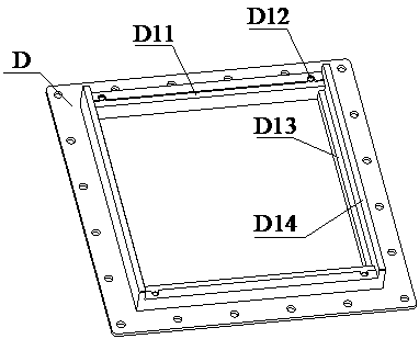
[0029] Such as image 3 As mentioned above, the test device for measuring the flow coefficient of the inlet hole of the flame tube is mainly composed of 1 piece of measuring section assembly A, 1 piece of exhaust assembly B, 1 piece of air inlet orifice plate C, 1 piece of support frame D, and 1 piece of rubber gasket E , 1 piece of rubber gasket F, and 2 pieces of pad K.

[0030]The measuring section component A is a rectangular channel structure, and the middle part of the measuring section component A is provided with a rectangular opening. The exhaust component B is a cylinder structure. The air intake end is a rectangular opening, and the support frame D is a plate-shaped opening structure. The support frame D is set between the rectangular opening in the middle of the measurement section component A and the air intake end of the exhaust component B. There is a place in the middle of the support frame D that can be placed The rectangular hollow of the air inlet orifice p...


PUM


Abstract

The invention belongs to the field of gas turbine engines, and discloses a test device and method for measuring flow coefficients of flame tube air inlets. The test device comprises a measuring section assembly, an exhaust assembly, an air inlet plate, a support frame and filler blocks. The measuring section assembly simulates flowing of air flow in two channels of a combustion chamber. The exhaust assembly simulates an inner cavity space of a flame tube, and an original method of obtaining air flow of the air inlets by using two flowmeters on secondary flow channels is replaced by an air exhaust measuring method to carry out measurement at an outlet of the exhaust assembly so as to increase air inlet flow measuring precision. The exhaust assembly is processed by using polymethyl methacrylate materials to carry out visualized analysis of air inlet exit flow field, test precision of flow coefficient data is improved, and complexity of test pieces is reduced. Test data can be conveniently used for calibration of calculation models of one-dimensional flow analysis software and three-dimensional commercial CFD software, and verification of annular combustion chamber flow distribution tests.

Description

technical field [0001] The invention belongs to the field of gas turbine engines, and more specifically relates to a test device and method for measuring the flow coefficient of a flame tube inlet hole. Background technique [0002] The flow coefficient of the inlet hole of the flame tube is a very important design data in the design and development of the combustion chamber. Different structures and even different sizes of the inlet hole will lead to different flow coefficients. Since there are many factors affecting the flow coefficient, it is necessary to obtain Highly accurate flow coefficient data can only be obtained experimentally. [0003] At present, there are generally two ways to measure the flow coefficient data through the test method as follows: 1) figure 1 The shown does not consider the influence of the flow of the secondary flow in the two channels of the combustion chamber, the air is directly discharged to the indoor atmosphere through the air inlet orifi...

Claims


Application Information

Patent Timeline
Patent Type & Authority Patents(China)
IPC IPC(8): G01F1/34
CPCG01F1/34
Inventor 彭中九陈盛王志凯罗莲军蔡茂胡好生
Owner CHINA AVIATION POWER MACHINE INST
Learn More