
Vibration signal combined denoising method

A vibration signal and signal technology, which is applied in the field of joint noise reduction of vibration signals based on wavelet transform modulus maximum value and independent component analysis, can solve the problem of poor separation effect, monitoring of equipment operating status, fault diagnosis interference, and inability to solve single-channel noise. ICA underdetermined problem and other problems, to achieve the effect of obvious features, poor separation effect, and beneficial fault diagnosis

Inactive Publication Date: 2017-08-08
BEIJING INFORMATION SCI & TECH UNIV
View PDF3 Cites 11 Cited by
  • Summary
  • Abstract
  • Description
  • Claims
  • Application Information

AI Technical Summary

Problems solved by technology

[0002] Due to the large amount of noise contained in the vibration signal of mechanical equipment, the existence of noise has brought great interference to the monitoring of equipment operation status and fault diagnosis.
In the existing noise reduction methods, ICA can only be applied to overdetermined blind source separation where the number of observed signal sources is not less than the number of signal sources. It cannot solve the underdetermined problem of single-channel ICA, and there are still separations caused by improper input vibration signals. The problem of poor performance

Method used


Image

  • Vibration signal combined denoising method
  • Vibration signal combined denoising method
  • Vibration signal combined denoising method

Examples


Embodiment Construction

[0015] The present invention will be described in detail below in conjunction with the accompanying drawings and embodiments.

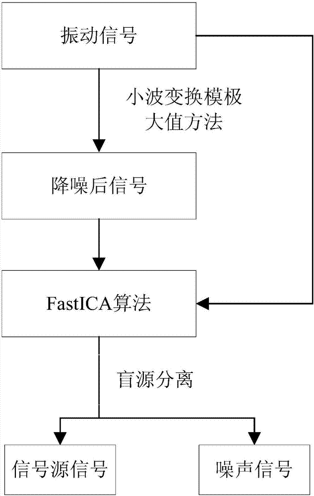
[0016] Such as figure 1 As shown, the present invention provides a method for joint noise reduction of vibration signals based on wavelet transform modulus maximum and independent component analysis, the method comprising the following steps:

[0017] 1) Perform wavelet transform modulus maxima decomposition on the collected vibration signal x(t), reconstruct the signal to obtain the noise-reduced signal, where t represents time;

[0018] The specific process is as follows:

[0019] 1.1) Perform wavelet decomposition on the vibration signal x(t).

[0020] According to the characteristics of the vibration signal, the number of decomposition scales is preferably 5, and the number of decomposition scales is selected as a db3 wavelet base with good compact support, orthogonality and relatively high vanishing moment.

[0021] 1.2) Calculate the modulus ...


PUM


Abstract

The present invention relates to a vibration signal combined denoising method. The method comprises the following steps of decomposing a wavelet transform modulus maximum of a vibration signal, and figuring out the positions of modulus maximum points and modulus maximum points corresponding to a wavelet transform coefficient on each scale; selecting a maximum wavelet decomposition scale J, adopting a pre-set threshold value T on the above scale as a search threshold, reserving the points of the modulus maximum points larger than T, removing the points of the modulus maximum points smaller than T and obtaining a new modulus maximum point on the scale J; searching a new modulus maximum point on the scale J-1 and positioned within a point set sequence in the neighborhood of the scale J; on the condition of the scale J=1, reserving the corresponding extreme value points of the scale J=1 at the positions of extreme value points of the scale J=2, while setting the values of extreme value points at all the rest positions to be 0; through the alternating projection process, obtaining a modulus maximum value on each scale and a reconstructed wavelet coefficient at the above position, and obtaining a reconstructed signal through inverse transform based on the obtained wavelet coefficient; based on the FastICA algorithm, subjecting a denoised signal and the vibration signal to blind source separation; and completing the combined denoising treatment on the vibration signal.

Description

technical field [0001] The invention relates to a vibration signal noise reduction method, in particular to a vibration signal joint noise reduction method based on wavelet transform modulus maximum and independent component analysis. Background technique [0002] Because the vibration signal of mechanical equipment contains a lot of noise, the existence of noise has brought great interference to the monitoring and fault diagnosis of equipment operation status. In the existing noise reduction methods, ICA can only be applied to overdetermined blind source separation where the number of observed signal sources is not less than the number of signal sources. It cannot solve the underdetermined problem of single-channel ICA, and there are still separations caused by improper input vibration signals. The problem of poor performance. Contents of the invention [0003] In view of the above problems, the object of the present invention is to provide a joint noise reduction method...

Claims


Application Information

Patent Timeline
Patent Type & Authority Applications(China)
IPC IPC(8): G06K9/00
CPCG06F2218/06
Inventor 蒋章雷徐小力左云波吴国新
Owner BEIJING INFORMATION SCI & TECH UNIV
Learn More