A multi-processor permanent magnet brushless direct current motor combined speed regulation system

A permanent magnet brushless DC and brush DC motor technology, which is applied in the direction of single motor speed/torque control, control system, motor control, etc., can solve the problem of increasing the size and cost of brushless DC motors, and the inability of the motor to run continuously and stably. Reduce the continuity of motor operation and other issues

Pending Publication Date: 2017-08-04
LANZHOU UNIVERSITY OF TECHNOLOGY
View PDF7 Cites 1 Cited by
  • Summary
  • Abstract
  • Description
  • Claims
  • Application Information

AI Technical Summary

Problems solved by technology

[0003] The existing brushless DC motor speed control system has the following defects and deficiencies: (1) The position sensor is used to detect the rotational position of the rotor, which further increases the size and cost of the brushless DC motor, and at the same time, the signal transmission cable of the position sensor is easily disturbed by the external environment , to reduce the continuity of motor operation; (2) The non-position rotor position signal detection method is single, only using the back EMF pulse method or the stator terminal voltage analog acquisition method, and does not combine the two methods of digital and analog to determine the rotor rotation position ; (3) Only one processor is used for drive control without combining the advantages of multi-processing joint operation. If the control board processor fails, the motor cannot run continuously and stably; (4) The motor drive control bridge adopts a single bridge operation mode, When a power electronic device on any bridge wall fails, the brushless DC motor needs to be shut down immediately for maintenance

Method used


Image

  • A multi-processor permanent magnet brushless direct current motor combined speed regulation system
  • A multi-processor permanent magnet brushless direct current motor combined speed regulation system
  • A multi-processor permanent magnet brushless direct current motor combined speed regulation system

Examples


Embodiment Construction

[0033] The present invention will be further described in detail below in conjunction with specific embodiments, which are explanations of the present invention rather than limitations.

[0034] The invention has the advantages of diversified motor rotor position data detection functions, multi-processor joint operation and double drive bridge drive, and is suitable for the technical field of high-precision brushless DC motor speed regulation.

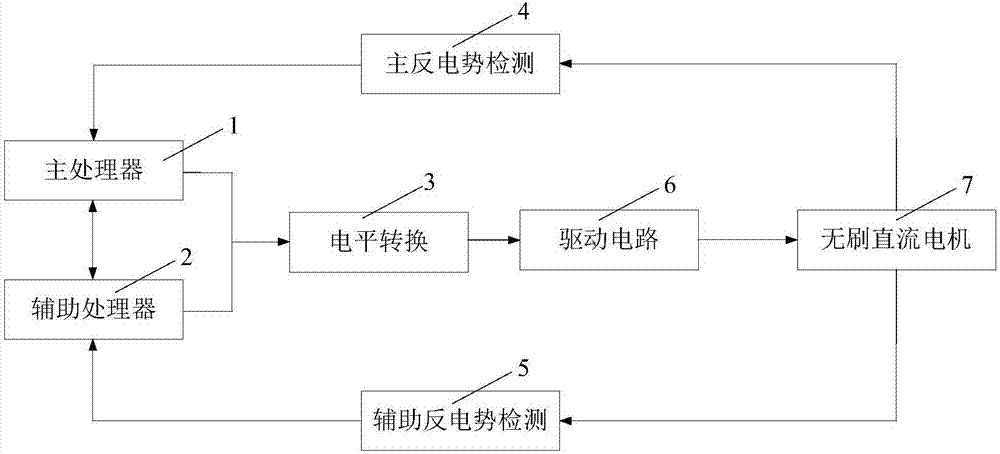
[0035] Such as figure 1 As shown, the present invention includes a brushless DC motor 7, a main processor module 1, an auxiliary processor module 2, a level conversion module 3, a main back EMF detection module 4, an auxiliary back EMF detection module 5 and a drive circuit module 6; wherein ,

[0036] Both the main processor module 1 and the auxiliary processor module 2 are used to collect the rotor position of the brushless DC motor 8, and respectively output digital PWM signals for controlling the rotational speed of the brushless ...


PUM


Abstract

A multi-processor permanent magnet brushless direct current motor combined speed regulation system of the invention comprises a brushless direct current motor, a main processor module, an auxiliary processor module, a level conversion module, a main counter potential detection module, an auxiliary counter potential detection module and a drive circuit module. The main processor module and the auxiliary processor module interact with each other and are both used to collect the rotor position of the brushless direct current motor and separately output digital PWM signals for controlling the rotational speed of the brushless direct current motor through the detected rotor rotation position. Digital PWM output terminals of the main processor module and the auxiliary processor module are separately connected to a level conversion module converting 3.3V level signals into 12V level signals. The level conversion module is connected to a drive circuit module driving the brushless direct current motor. The brushless direct current motor feed motor rotor position signals back to a main processor module interruption input port and an auxiliary processor module analog quantity acquisition port through the main counter potential detection module and the auxiliary counter potential detection module.

Description

technical field [0001] The invention relates to the technical field of brushless DC motor speed regulation, in particular to a multi-processor permanent magnet brushless DC motor combined speed regulation system. Background technique [0002] With the rapid development of power electronics technology and devices, brushless motor BLDC gradually replaces traditional brushed motors with its advantages of no carbon brush wear, no commutation sparks, low noise, low maintenance costs, high operating efficiency and long service life. And it is widely used in emerging technology fields such as home appliances, model airplanes, and electric vehicles. The brushless motor must judge the rotation position of the rotor when adjusting the speed. The controller uses the rotation position fed back by the rotor to commutate according to the set control strategy, so that the motor can rotate continuously and reliably in each operation cycle. In the field of position sensor detection brushles...

Claims


Application Information

Patent Timeline
IPC IPC(8): H02P6/08H02P29/028H02P6/182
CPCH02P6/08H02P6/182
Inventor 杨沛豪王晓兰刘向辰寇水潮
Owner LANZHOU UNIVERSITY OF TECHNOLOGY
Why Eureka
Try Eureka