Method for reducing ablation problem in weapon body pipe by using magnetic control plasma

A plasma and body tube technology, applied in the field of weapons, can solve the problems of long production cycle, high cost, and difficulty in popularization and use, and achieve the effect of reducing wall temperature, reducing efficiency, and weakening heat transfer capacity

Inactive Publication Date: 2017-08-04
ACADEMY OF ARMORED FORCES ENG PLA
View PDF4 Cites 5 Cited by
  • Summary
  • Abstract
  • Description
  • Claims
  • Application Information

AI Technical Summary

Problems solved by technology
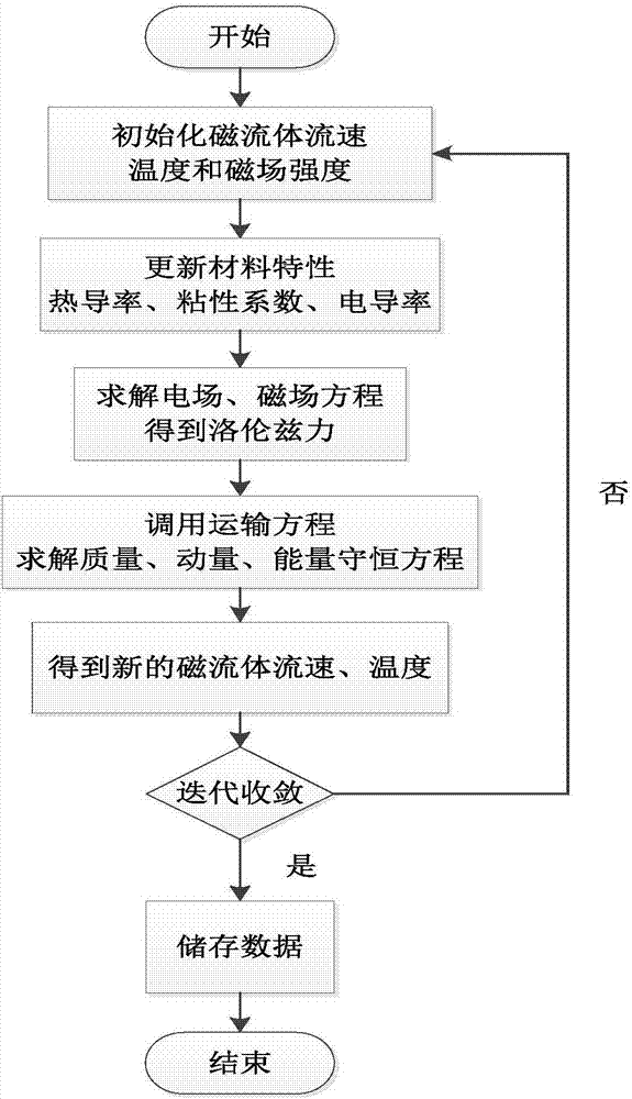
However, the manufacturing process of the composite barrel is complicated, the production cycle is long, and the cost is high, so it is not easy to popularize and use

Method used


Image

  • Method for reducing ablation problem in weapon body pipe by using magnetic control plasma
  • Method for reducing ablation problem in weapon body pipe by using magnetic control plasma
  • Method for reducing ablation problem in weapon body pipe by using magnetic control plasma

Examples


Embodiment 1

[0034] Discuss the influence of electromagnetic intensity B on the temperature of the inner wall of the cylinder:

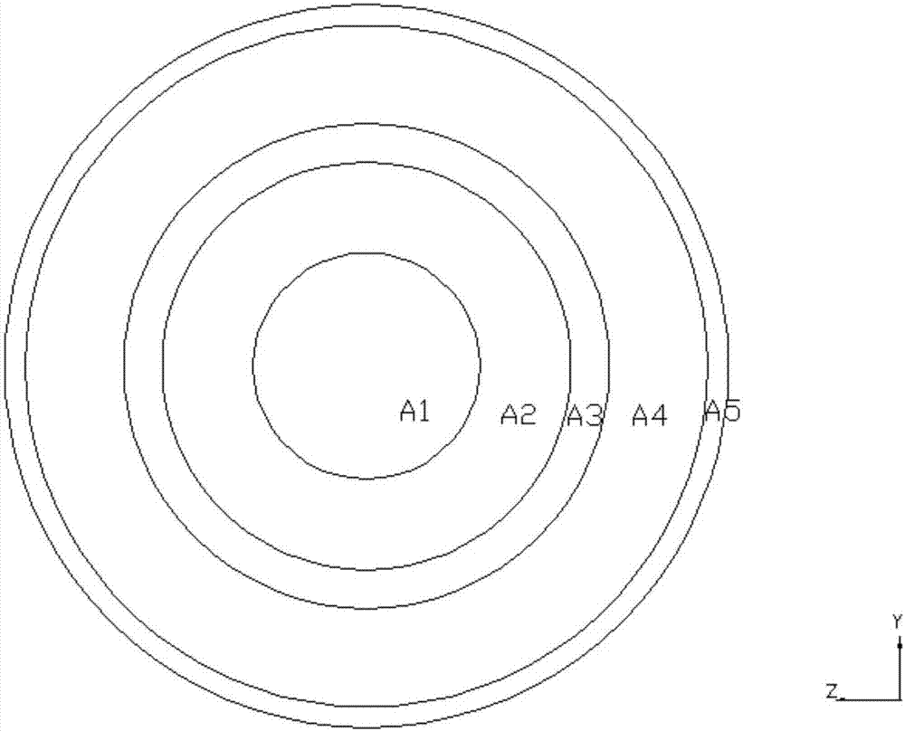
[0035] Bring B=0T, B=0.5T, B=1T, B=2T into the solution process of turbulent kinetic energy respectively, image 3 shows the turbulent kinetic energy distribution at B=0T, Figure 4 shows the turbulent kinetic energy distribution for B=0.5T, Figure 5 The temperature curves of the inner wall of the cylinder under different magnetic fields are shown. It can be seen from the figure that the heat transfer of the high-temperature gas to the wall surface decreases after the external magnetic field is applied. With the increase of the magnetic field, the heat insulation effect is more obvious. This is because the magnetic field reduces the turbulent kinetic energy of the fluid, and its heat transfer ability is correspondingly weakened.

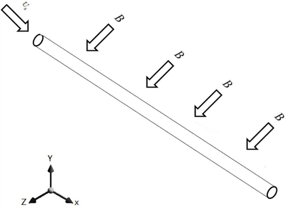
[0036] It can be seen that the magnetic field perpendicular to the flow direction of the conductive gas can change its flow field s...

Embodiment 2

[0038] Discuss the effect of conductivity σ on the temperature of the inner wall of the cylinder:

[0039] In the case of applying a 0.5T magnetic field, set the conductivity of the plasma to 0 to 10000S / m, Figure 6 The temperature curves of the inner wall under different conductivity are shown. When the conductivity σ is lower than 1000S / m, the induced current density of the fluid under the action of the magnetic field is small, and the Lorentz force on the magnetic fluid is correspondingly reduced, and the turbulence is suppressed. The effect is weak. Therefore, the temperature change curve basically coincides with the curve with zero conductivity. When the conductivity continues to increase to 5000S / m, the induced current density increases, and it can be seen that the temperature curve has changed significantly, and the temperature of the inner wall of the cylinder has been effectively reduced, and as the conductivity continues to rise, The insulation effect is gradually...


PUM

PropertyMeasurementUnit
Magnetic field strengthaaaaaaaaaa
Conductivityaaaaaaaaaa

Abstract

The invention discloses a method for using magnetron plasma to reduce the ablation problem in the barrel of a weapon and to calculate the turbulent kinetic energy of the plasma, comprising setting a magnetic field outside the barrel, the direction of the magnetic field is perpendicular to the axis of the barrel, and The magnetic field strength along the radial direction of the barrel is consistent, and the high-temperature conductive gas formed by the combustion of gunpowder forms a magnetically confined plasma in the barrel under the action of the magnetic field, reducing the turbulent kinetic energy of the magnetically confined plasma. The method of using magnetron plasma to reduce the ablation problem in the weapon barrel of the present invention has the advantage that the magnetic field perpendicular to the flow direction of the conductive gas can change its flow field structure and effectively reduce its heat transfer capacity. When the magnetic field strength is 2T, the wall surface temperature decreases by 22.6% compared with that without magnetic field.

Description

technical field [0001] The invention relates to the technical field of weapons. More specifically, the present invention relates to a method of using magnetron plasma to reduce the problem of ablation in the barrel of a weapon. Background technique [0002] With the research and development of magnetic fluid power generation technology, relevant scholars at home and abroad have found that the detonation of high-energy explosives in the combustion chamber can form high-temperature and high-pressure plasma, and the gas has good conductivity. MHD Corporation of the United States developed a magnetic fluid power generation device in the 1960s: adding ionized seeds to the C4 composite powder column, when the external magnetic field is 2.8T, the maximum current generated by the ionized gas in the device reaches 260kA. The experiment of Beijing Institute of Technology measured that the maximum electrical conductivity of gas is 18000S / m when the density of TNT is 1.520g / cm3. The I...

Claims


Application Information

Patent Timeline
IPC IPC(8): F41C27/06
CPCF41C27/06
Inventor 毛保全李程冯帅钟孟春杨雨迎白向华李华徐振辉王艳峰王之千李晓刚兰图李俊辛学敏
Owner ACADEMY OF ARMORED FORCES ENG PLA
Why Eureka
Try Eureka