Sintered body, sputtering target comprising sintered body and thin film formed by using spattering target
A technology of sintered body and sputtering target, which is applied in sputtering plating, ion implantation plating, coating, etc. It can solve the problems of not being able to maintain the excellent characteristics of ZnS, reduce the transmittance, and not suitable for devices, and achieve good water resistance properties, low volume resistivity, and improved productivity
- Summary
- Abstract
- Description
- Claims
- Application Information
AI Technical Summary
Problems solved by technology
Method used
Image
Examples
Embodiment 1
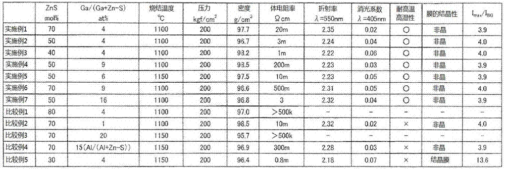
[0091] Deploy Ga 2 o 3 powder, ZnO powder to achieve the atomic ratio shown in Table 1, and mix them. Next, the mixed powder was calcined in the atmosphere at a temperature of 1050° C., and then wet pulverized (using ZrO 2 Microbeads) crushed to an average particle size of 2 μm or less, dried and sieved with a sieve with a mesh size of 150 μm. Then, this finely pulverized powder and ZnS powder were mixed in the compounding ratio described in Table 1, and then, in an Ar atmosphere at a temperature of 1100°C and a pressure of 200kgf / cm 2 hot-pressed sintering conditions.
[0092] Then, this sintered body was finished into a sputtering target shape by machining. The volume resistance and relative density of the obtained target were measured. As shown in Table 1, the relative density was 97.7%, the volume resistance was 0.02Ω·cm, and stable DC sputtering was possible. As a result of analyzing the component composition of the target, it was confirmed that the compounding ratio...
Embodiment 2
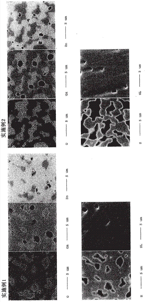
[0097] Deploy Ga 2 o 3 powder, ZnO powder to achieve the atomic ratio shown in Table 1, and mix them. Next, the mixed powder was calcined in the atmosphere at a temperature of 1050° C., and then wet pulverized (using ZrO 2 Microbeads) crushed to an average particle size of 2 μm or less, dried and sieved with a sieve with a mesh size of 150 μm. Then, the finely pulverized powder and the ZnS powder were mixed in the compounding ratio described in Table 1, and hot press sintering was performed in the same manner as in Example 1. Then, this sintered body was finished into a sputtering target shape by machining. The volume resistance and relative density of the obtained target were measured. As shown in Table 1, the relative density was 96.7%, the volume resistance was 0.003Ω·cm, and stable DC sputtering was possible. In addition, the target tissue was observed with EMPA (Electron Probe Microanalyzer), and the results were as follows: figure 1 As shown in , it was confirmed th...
Embodiment 3
[0100] Deploy Ga 2 o 3 powder, ZnO powder to achieve the atomic ratio shown in Table 1, and mix them. Next, the mixed powder was calcined in the atmosphere at a temperature of 1050° C., and then wet pulverized (using ZrO 2 Microbeads) crushed to an average particle size of 2 μm or less, dried and sieved with a sieve with a mesh size of 150 μm. Then, the finely pulverized powder and the ZnS powder were mixed in the compounding ratio described in Table 1, and hot press sintering was performed in the same manner as in Example 1. Then, this sintered body was finished into a sputtering target shape by machining. The volume resistance and relative density of the obtained target were measured. As shown in Table 1, the relative density was 98.2%, the volume resistance was 0.001Ω·cm, and stable DC sputtering was possible. In addition, as a result of observing the target structure with EMPA (electron probe microanalyzer), it was confirmed that oxides containing Ga, Zn, and O were fo...
PUM
| Property | Measurement | Unit |
|---|---|---|
| electrical resistivity | aaaaa | aaaaa |
| refractive index | aaaaa | aaaaa |
| refractive index | aaaaa | aaaaa |
Abstract
Description
Claims
Application Information
 - R&D Engineer
- R&D Manager
- IP Professional
- Industry Leading Data Capabilities
- Powerful AI technology
- Patent DNA Extraction
Browse by: Latest US Patents, China's latest patents, Technical Efficacy Thesaurus, Application Domain, Technology Topic, Popular Technical Reports.
© 2024 PatSnap. All rights reserved.Legal|Privacy policy|Modern Slavery Act Transparency Statement|Sitemap|About US| Contact US: help@patsnap.com


