Vehicle-mounted laser radar control method, device and vehicle-mounted equipment
A vehicle-mounted lidar and lidar technology, which is used in measurement devices, vehicle parts, transportation and packaging, etc., and can solve problems such as large blind spots for lidar detection.
- Summary
- Abstract
- Description
- Claims
- Application Information
AI Technical Summary
Problems solved by technology
Method used
Image


Examples
Embodiment 1
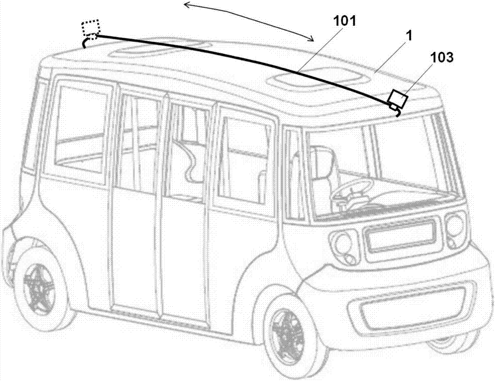
[0068] In the embodiment of the present invention, the vehicle-mounted laser radar is not installed in a fixed position, but driven by certain mechanical components to move on the vehicle body. figure 1 A minimalist implementation of a movable vehicle-mounted laser radar is given, wherein the vehicle-mounted laser radar includes a guide rail 101, a sliding bracket (not shown in the figure) and a multi-line laser radar 103; the multi-line laser radar 103 is installed On the sliding bracket, the sliding bracket is arranged on the guide rail 101, and the guide rail 101 is fixed on the top of the car body 1 through two ends; the guide rail 101 is provided with a toothed chain, and the sliding bracket includes a driving motor and a gear, and the driving motor is driven through the gear. , the rotating gear meshes with the chain and rolls, thereby driving the sliding bracket and the lidar 103 on it to move back and forth on the guide rail 101 . As a minimalist implementation, the li...
Embodiment 2
[0082] In an embodiment of the present invention, judging whether there is a key detection blind spot in the lidar according to the perception and control data includes:
[0083] Determine whether the lidar has a detection blind spot according to the perception data;
[0084] When there is a detection blind zone, judge the influence of each detection blind zone on the driving safety of the vehicle according to the perception and control data;
[0085] The blind detection areas are sorted according to their impact on vehicle driving safety, and one or more blind detection areas that are ranked first and / or whose impact exceeds a preset threshold are determined as key blind detection areas.
[0086] Wherein, in one embodiment of the present invention, it is determined whether the lidar has a detection blind spot according to the perception data of the lidar and / or other sensors. Theoretically speaking, due to the limitation of the detection range and / or detection accuracy, the ...
Embodiment 3
[0098] In an embodiment of the present invention, controlling the lidar to move to an effective detection position for the critical detection blind area includes:
[0099] determining an effective detection location for each critical detection blind spot based on the perception and control data;
[0100] Planning the movement path of the lidar according to the effective detection position;
[0101] Drive the lidar to move according to the planned motion path.
[0102] Wherein, in the embodiment of the present invention, the effective detection position is the position of the lidar that can effectively detect the critical detection blind area. The effective detection position is usually determined comprehensively according to the working capability of the lidar; typically, it is determined according to the detectable range of the lidar. For example, for a single key detection blind area, since the range of the key detection blind area is usually not greater than the detectabl...
PUM
 Abstract
Description
Claims
Application Information
 - R&D
- Intellectual Property
- Life Sciences
- Materials
- Tech Scout
- Unparalleled Data Quality
- Higher Quality Content
- 60% Fewer Hallucinations
Browse by: Latest US Patents, China's latest patents, Technical Efficacy Thesaurus, Application Domain, Technology Topic, Popular Technical Reports.
© 2025 PatSnap. All rights reserved.Legal|Privacy policy|Modern Slavery Act Transparency Statement|Sitemap|About US| Contact US: help@patsnap.com