
Conveying method and system device of side wires obtained by cutting of welding machine

A technology of conveying device and welding machine, which is used in shearing devices, accessories of shearing machines, conveyors, etc.

Active Publication Date: 2017-08-04
BAOSHAN IRON & STEEL CO LTD
View PDF4 Cites 1 Cited by
  • Summary
  • Abstract
  • Description
  • Claims
  • Application Information

AI Technical Summary

Problems solved by technology

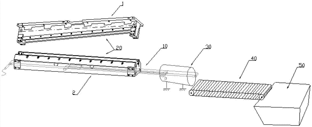
[0003] In order to solve the above problems, the object of the present invention is to provide a welding machine shearing edge wire efficient delivery method and system device thereof, which is especially suitable for slender strip waste such as cold rolling laser welding machine shearing edge wire. Its system device overcomes the problem that the waste shear wire cut off during the welding of high-strength steel by the laser welding machine cannot be effectively conveyed, which causes the shear wire to affect the surrounding equipment. The system controls the shear wire to fall through compressed gas At the same time, the fixed-point delivery method of magnetic adsorption technology is used to accurately transport the cut slender strips of trimmings to the waste hopper, which eliminates the problem of abnormal pop-up of trimmings after shearing and the problem of conventional transportation. Cross-running and jamming problems effectively improve the effectiveness of laser welding machine cutting edge wire delivery, and stabilize the quality of laser welding weld seams

Method used


Image

  • Conveying method and system device of side wires obtained by cutting of welding machine
  • Conveying method and system device of side wires obtained by cutting of welding machine
  • Conveying method and system device of side wires obtained by cutting of welding machine

Examples


Embodiment

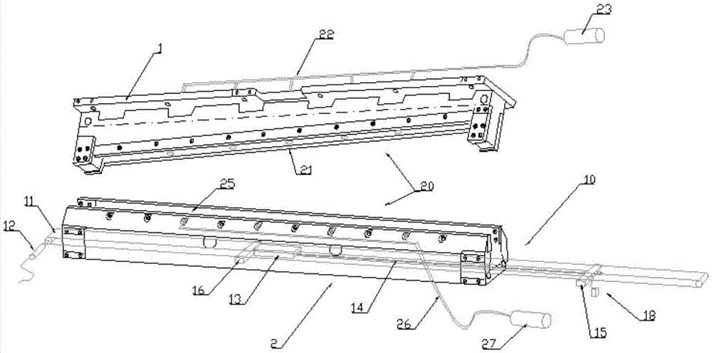
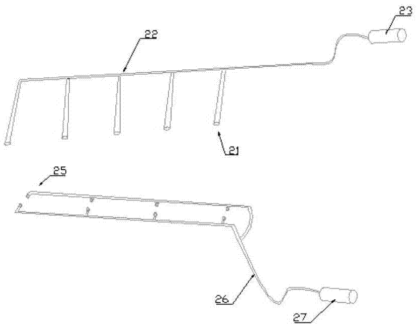
[0050] High-efficiency conveying system for welding machine cutting side wire. During the secondary shearing process of the welding machine, compressed gas is injected into the built-in nozzle of the upper scissors, and the cut side wire is blown down to the waste belt inside the lower scissors. The lower scissors The side nozzle sprays compressed gas at the same time to blow the falling edge wire to the middle of the waste belt to prevent it from being stuck into the belt when it is at the edge of the belt. 2 seconds before the end of the blowing, the magnetic suction cup is energized to generate magnetic adsorption to cut the edge wire, and the suction cup drives the wire. The rod assembly and the waste belt move synchronously, conveying the sucked cut edge wire to the end of the waste belt, and at the same time the suction cup is powered off to release the edge wire, and the edge wire enters the limit guide blowing part with the running belt, and the part blows compressed gas...


PUM


Abstract

The invention discloses a conveying method of side wires obtained by cutting of a welding machine. The conveying method is used for conveying elongated wastes such as side wires obtained by cutting of a cold-rolling laser welding machine. A conveying system device of side wires obtained by cutting of the welding machine comprises a sucking and conveying mechanism (10) for side wires obtained by cutting, a gas blowing and pressing mechanism (20), a side wire guiding and blowing mechanism (30) and an external outputting and conveying mechanism (40), and is characterized in that: during the secondary cutting process of the welding machine, a longitudinal gas injecting and blowing assembly arranged in upper shears of the gas blowing and pressing mechanism (20) injects and blows compressed gas from a nozzle in the bottoms of the upper shears and blows off the side wires cut off onto a waste conveying belt (11 ) arranged in lower shears. According to the conveying method disclosed by the invention, the conveying of the side wires obtained by cutting of the laser welding machine is effectively improved, and the quality of a welding seam welded by the laser welding machine is stabilized.

Description

technical field [0001] The invention relates to a method and a system device for conveying cut waste materials of equipment such as welding machines, and is particularly suitable for a method and a system device for conveying slender waste materials such as cut side wires of metallurgical cold-rolled laser welding machines. Background technique [0002] In the field of metallurgy, the cold-rolled acid-rolled laser welding machine is mainly used for welding hot-rolled strip steel with a thickness of 2mm-5mm and a hardness of HR30Te between 42-96. When welding high-strength steel with a hardness greater than 80, in order to ensure the shearing effect, the welding machine usually adopts a secondary shearing method, that is, the first shearing is normal shearing to cut off the leading and tailing scraps with a protruding length of about 60mm. The edge, followed by the second cut is the trimming cut. Cut off the tape head and tape tail with a protruding length of 0.2mm to 0.5mm ...

Claims


Application Information

Patent Timeline
IPC IPC(8): B23D33/00B65G47/22B65G15/58
CPCB23D33/00B65G15/58B65G47/22
Inventor 陈杰张博林柯重建沈馗夏珅
Owner BAOSHAN IRON & STEEL CO LTD
Learn More