
Wet etching device, wet etching method and wafer chip

A wet etching, wafer technology, applied in the direction of electrical components, semiconductor/solid-state device manufacturing, circuits, etc., can solve problems such as difficult to control, low efficiency, wafer surface contamination, etc., to achieve high speed, reduce The effect of surface contamination

Pending Publication Date: 2017-07-28
SHENZHEN PHOGRAIN INT TECH DEV
View PDF0 Cites 2 Cited by
  • Summary
  • Abstract
  • Description
  • Claims
  • Application Information

AI Technical Summary

Problems solved by technology

[0007] (2) The corrosive liquid of wet corrosion is generally harmful to the human body. Therefore, it needs to be carried out in a well-ventilated environment, which is difficult to control and has low efficiency. The manual investment is relatively large and it is difficult to achieve mass production
[0008] (3) During the wet etching process of horizontally placed wafers, the corrosion waste liquid can only be thrown out by centrifugal force, which is likely to cause contamination on the surface of the wafer

Method used


Image

  • Wet etching device, wet etching method and wafer chip
  • Wet etching device, wet etching method and wafer chip

Examples


Embodiment 1

[0083] First, a photoresist is coated on the surface of the wafer, and then the desired pattern is obtained on the surface of the wafer through a photolithography process. The surface of the wafer causes a chemical reaction of the photoresist in the exposed area, and then dissolves and removes the photoresist in the exposed or unexposed area by developing technology, so that the pattern on the mask plate is copied to the photoresist film, and finally uses Wafers are patterned using wet etching techniques.

Embodiment 2

[0085] The area where the metal film is not needed is covered with photoresist, and the surface of the wafer is covered with a layer of metal by the method of coating, so that the metal film is only connected to the substrate in the required area, and finally placed on the wet etching device , Through the wet etching device, the fluidity of the stripping solution is increased, and the impact kinetic energy of the stripping solution on the wafer is improved, which effectively improves the stripping rate of the photoresist, thereby improving the uniformity of corrosion (metal stripping). As the photoresist dissolves, the metal on it also falls off, leaving the desired metal pattern.

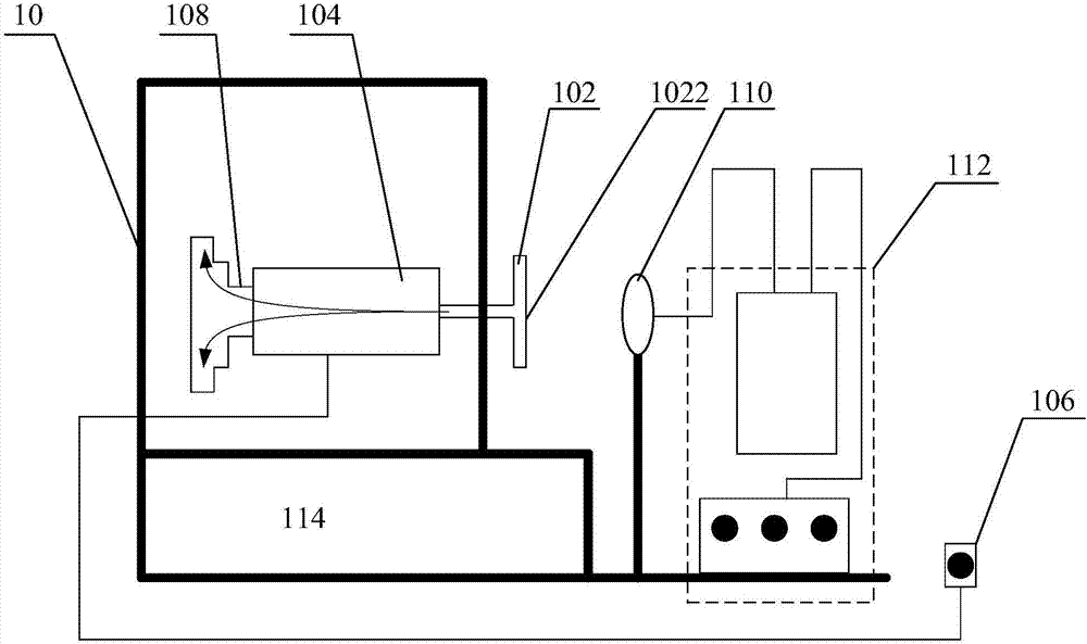
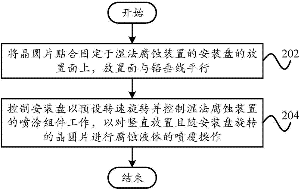
[0086] combine figure 1 and figure 2 As shown, in any of the above-mentioned embodiments, preferably, a wet etching device is used to wet-etch the wafer, which specifically includes: step 202, attaching and fixing the wafer to the mounting plate 102 of the wet-etching device On the placement sur...


PUM


Abstract

The present invention provides a wet etching device, a wet etching method and a wafer chip, wherein the wet etching device comprises a shell support and a rotating assembly arranged on the shell support. The rotating assembly comprises a rotatable installation disc, the placement surface of the installation disc is parallel with a plumb line and is used to place a wafer on which the wet etching is to be carried out. By the technical scheme of the present invention, the fluidity of an etching liquid is increased, and the uniformity and the reliability of a wet etching technology are improved effectively.

Description

technical field [0001] The invention relates to the technical field of wet etching, in particular, to a wet etching device, a wet etching method and a wafer chip. Background technique [0002] With the development of data and information technology, the demand for semiconductor chips and III-V compound optical chips is also increasing, especially for the manufacturing process requirements of optical chips, the complexity and consistency of which are constantly increasing. Among them, wet etching technology is A very important step in chip manufacturing technology, the wet etching process has the following characteristics: [0003] (1) The result of wet etching will be affected by many factors, such as the concentration of the etching liquid, the surface quality of the wafer, the temperature and fluidity of the etching liquid, etc. [0004] (2) In order to obtain a uniform etched surface, the time of the etchant on the wafer must be reduced, which is also beneficial to avoid...

Claims


Application Information

Patent Timeline
Patent Type & Authority Applications(China)
IPC IPC(8): H01L21/67H01L21/306
CPCH01L21/30604H01L21/30612H01L21/6708
Inventor 陆一峰刘格杨彦伟刘胜宇曾建武
Owner SHENZHEN PHOGRAIN INT TECH DEV
Learn More