
Grate-firing boiler with high efficiency and low nitrogen combustion

A low-nitrogen combustion and chain boiler technology, which is applied in the direction of combustion chamber, combustion method, combustion equipment, etc., can solve the problems of low NOx combustion technology of floor-fired boilers without retrofitting engineering application examples, etc.

Active Publication Date: 2017-07-28
YANTAI LONGYUAN POWER TECH
View PDF10 Cites 2 Cited by
  • Summary
  • Abstract
  • Description
  • Claims
  • Application Information

AI Technical Summary

Problems solved by technology

[0005] At present, the engineering examples of reducing pollutant emissions from floor-fired boilers mainly focus on dust removal and desulfurization outside the furnace. Some boilers have considered the application of SNCR to remove NOx, but there is no retrofit project application for the low-NOx combustion technology of floor-fired boilers. example
At present, the low-nitrogen combustion technology is basically not used in domestic floor-fired boilers, and most of their emissions are between 300 and 800 mg / Nm3. With the increasingly stringent national environmental protection requirements, these boilers are facing the requirements of transformation and upgrading.

Method used


Image

  • Grate-firing boiler with high efficiency and low nitrogen combustion

Examples


Embodiment Construction

[0025] In order to make the purpose, technical solutions and advantages of the embodiments of the present invention clearer, the technical solutions in the embodiments of the present invention will be clearly and completely described below in conjunction with the drawings in the embodiments of the present invention. Obviously, the described embodiments It is a part of embodiments of the present invention, but not all embodiments. Based on the embodiments of the present invention, all other embodiments obtained by persons of ordinary skill in the art without making creative efforts belong to the protection scope of the present invention.

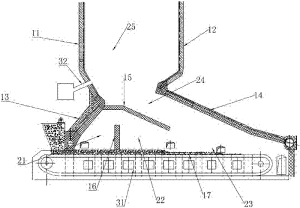
[0026] Please refer to figure 1 , figure 1 Schematic diagram of the structure of the layer fired chain boiler provided by the embodiment of the present invention.

[0027] The high-efficiency low-nitrogen combustion layer-fired chain boiler provided by the embodiment of the present invention includes a furnace body and a fire grate 17. The ...


PUM


Abstract

The invention discloses a grate-firing boiler with high efficiency and low nitrogen combustion. The grate-firing boiler comprises a boiler body and a fire grate, wherein the boiler body comprises a front arch, a rear arch, a left side wall, a right side wall, a first partition wall and a second partition wall which are annularly arranged; the fire gate is positioned below the boiler body and is positioned between the front arch and the rear arch; the first partition wall is arranged between the front arch and the rear arch and is positioned above the fire grate; the second partition wall is arranged above the first partition wall and a gap is reserved between the first partition wall and the second partition wall; the second partition wall extends from the front arch to the rear arch and crosses over the first partition wall; a gap is formed between the top end of the second partition wall and the rear arch; and a secondary air inlet is arranged on the boiler body and on a position towering above the front arch. The front arch, the fire grate, the first partition wall and the second partition wall as well as the left side wall and the right side wall are encircled to form a fire volatile area; the fire grate, the first partition wall, the second partition wall and the rear arch as well as the left side wall and the right side wall are encircled to form a main combustion reduction area; and the top end and the rear arch of the second partition wall as well as the left side wall and the right side wall are encircled into a cinder burnout area, thereby reducing pollution.

Description

technical field [0001] The invention relates to the technical field of boilers, in particular to a high-efficiency and low-nitrogen combustion layer-fired chain boiler. Background technique [0002] Layer-fired chain boiler is a very mature boiler type. It has been used for hundreds of years, mainly for heating and industrial steam supply. The main structural types currently used are: fixed grate furnace, chain grate furnace, coal thrower grate furnace, reciprocating grate furnace and vibrating grate furnace, etc. [0003] Because of its wide fuel applicability, low cost, convenient start and stop, and strong load regulation, the layer-fired chain boiler has inherent advantages in industrial applications and winter heating in my country. After decades of development, the market has a huge amount. According to the statistics of China Boiler Network, there are 620,300 boilers in my country, of which the number of small coal-fired boilers above 10 tons per hour accounts for on...

Claims


Application Information

Patent Timeline
IPC IPC(8): F23B10/00F23M9/00F23L9/00F23M5/06
CPCF23B10/00F23L9/00F23M5/06F23M9/00Y02E20/34
Inventor 王家兴崔节明王冠楠路亭伟程昌业彭建升董永胜
Owner YANTAI LONGYUAN POWER TECH
Learn More