Inductive igniter with flameout self-locking function

An inductive, igniter technology, applied in the field of gasoline engines, can solve the problems of misstarting the gasoline engine, the gasoline engine cannot be completely shut down, etc., to avoid false start, prevent the bad igniter, and realize the effect of flameout protection.

Active Publication Date: 2018-10-19
CHONGQING LIHUA AUTOMATION TECH CO LTD
View PDF5 Cites 0 Cited by
  • Summary
  • Abstract
  • Description
  • Claims
  • Application Information

AI Technical Summary

Problems solved by technology

[0006] In view of this, the object of the present invention is to provide an inductive igniter with flame-out self-locking function to solve the technical problems that the existing general-purpose gasoline engine igniter easily causes the gasoline engine to start incorrectly, the gasoline engine shakes and cannot be completely extinguished, etc.

Method used


Image

  • Inductive igniter with flameout self-locking function
  • Inductive igniter with flameout self-locking function
  • Inductive igniter with flameout self-locking function

Examples


Embodiment Construction

[0025] The present invention will be further described below with reference to the drawings and embodiments.

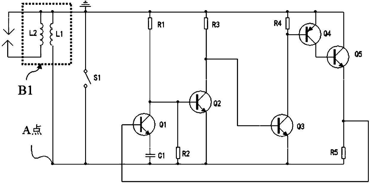
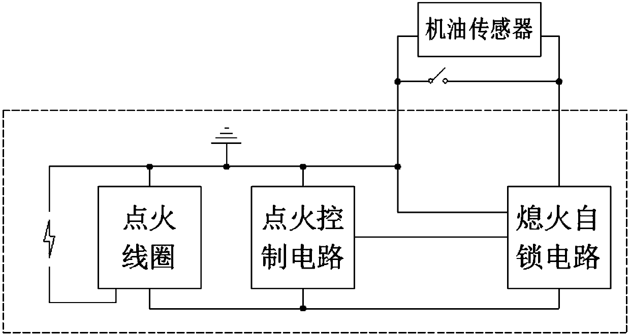
[0026] Such as Figure 4 As shown, the inductive igniter with flameout self-locking function of this embodiment includes an ignition coil B1 composed of a primary coil L1 and a secondary coil L2, and an ignition control circuit connected to the primary coil. The ignition control circuit is used to control ignition The coil generates high-voltage pulses, and further includes a flame-out self-locking circuit connected to the ignition control circuit, and the flame-out self-locking circuit is used to disable the ignition control circuit;

[0027] The ignition control circuit includes a first resistor R1, a second resistor R2, a third resistor R3, a fourth resistor R4, a fifth resistor R5, a first triode Q1, a second triode Q2, and a third triode Q3, the fourth transistor Q4, the fifth transistor Q5, and the first capacitor C1;

[0028] One end of the first resistor is connect...


PUM


Abstract

The invention discloses an electrical inductance type flame ignitor with the flameout self-locking function. The electrical inductance type flame ignitor comprises a flame ignition coil and a flame ignition control circuit, wherein the flame ignition coil is composed of a primary coil and a secondary coil; the flame ignition control circuit is connected with the primary coil and is used for controlling a high-voltage pulse generated by the flame ignition coil; the electrical inductance type flame ignitor further comprises a flameout self-locking circuit connected with the flame ignition control circuit; and the flameout self-locking circuit is used for enabling the flame ignition control circuit to malfunction. According to the electrical inductance type flame ignitor, through additionally arranging the flameout self-locking circuit, the problems that a gasoline engine is started by mistake and is switched off not thoroughly can be avoided; in addition, the electrical inductance type flame ignitor can be connected into an engine oil sensor to realize flameout protection when the engine oil gives an alarm; and moreover, the electrical inductance type flame ignitor can prevent an external power supply from being connected into the ignitor to avoid malfunction of the ignitor.

Description

Technical field [0001] The invention relates to the technical field of gasoline engines, in particular to an igniter of a gasoline engine. Background technique [0002] Traditional general gasoline engine igniters are mostly used as the instructions attached figure 1 The circuit structure shown, the working principle of the ignition control circuit is as follows: [0003] First, the primary coil L1 of the ignition coil B1 (i.e. the magneto stator) induces a set of electromotive force pulse waveforms (see figure 2 ); When the leading edge of the negative pulse of the L1 induced electromotive force arrives, the transistor Q2 cannot be turned on before the transistor Q3 due to the partial pressure of the resistor R1 and the resistor R2. After the transistor Q3 is turned on, the transistor Q4 and the transistor Q5 are turned on. After the transistor Q5 is turned on, the induced electromotive force induced by the primary coil L1 of the ignition coil B1 forms a loop through the primary ...

Claims


Application Information

Patent Timeline
Patent Type & Authority Patents(China)
IPC IPC(8): F02P3/04
CPCF02P3/0435
Inventor 何林张邦全张明鸿奚建平邓大海
Owner CHONGQING LIHUA AUTOMATION TECH CO LTD
Why Eureka
Try Eureka