Eureka AIR delivers breakthrough ideas for toughest innovation challenges, trusted by R&D personnel around the world.

Novel floatable solid foam scrubbing rod and preparation method thereof

A new type of foam discharge rod technology, which is applied in chemical instruments and methods, mining fluids, earthwork drilling, etc., can solve the problems of slow dissolution speed, small contact surface, shortening the dissolution time of foam discharge rods, etc., and achieves a simple and easy preparation method. It has the effect of improving foam stability and good compatibility.

Active Publication Date: 2017-07-28
陕西森瑞石油技术开发有限公司
View PDF11 Cites 11 Cited by
  • Summary
  • Abstract
  • Description
  • Claims
  • Application Information

AI Technical Summary

Problems solved by technology

The design of three fan blades increases the contact area between the foaming agent and the bottom well fluid to a certain extent, and shortens the dissolving time of the foam stripping rod in the bottom well fluid, but the preparation of this foam stripping rod is complicated and not easy. Easy to store and use
[0008] (1) The density of foam row sticks is usually 1.2 ~ 1.4g / cm 3 , greater than the wellbore fluid density 1.05 ~ 1.15g / cm 3 After being put into the wellbore, it will gradually sink into the bottom of the well. The deeper the foam row rod is immersed in the bottom of the well, the greater the force of the accumulated fluid pressure on the foam row rod, and the less likely it is to generate air bubbles, so that the foaming effect cannot be fully exerted, and serious Those who will block the bottom of the well;
[0009] (2) The contact surface between the cylindrical foam row rod and the bottom of the well is small, and the dissolution rate is relatively slow, which cannot effectively play the role of the foam row rod

Method used


Image

  • Novel floatable solid foam scrubbing rod and preparation method thereof
  • Novel floatable solid foam scrubbing rod and preparation method thereof
  • Novel floatable solid foam scrubbing rod and preparation method thereof

Examples


Embodiment 1

[0046] In this example, the components and proportions of several floating solid bubble bars are given, and the preparation methods of each bubble bar are given.

[0047] (1) Floatable solid bubble row stick SRP-1

[0048] The components and their ratios are: 50 kg of dodecyl ethoxy sulfobetaine, 15 kg of coconut monoethanolamide, 10 kg of thiourea, 5 kg of sodium chloride, 3 kg of polyvinyl alcohol, and 2 kg of sodium benzoate.

[0049] The preparation method of floating solid bubble stick SRP-1:

[0050] Step 1: Put 50 kg of dodecyl ethoxy sulfobetaine, 15 kg of coco-monoethanolamide, and 10 kg of thiourea into a container. After mixing, heat to 50° C., heat and dry for 3 hours.

[0051] Step 2: Then add 5 kg of sodium chloride, 3 kg of polyvinyl alcohol, and 2 kg of sodium benzoate to the container of step 1, mix well, start heating, gradually increase the temperature to 80°C, keep it for 5 hours until the material is dried;

[0052] Step 3: After the material obtained in step 2 is co...

Embodiment 2

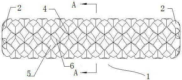
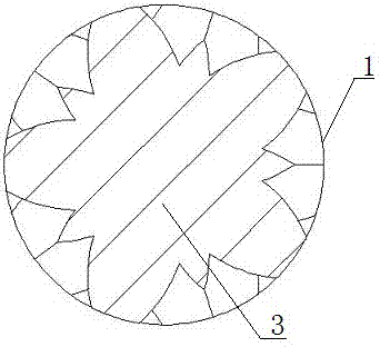
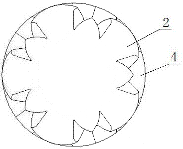
[0078] The above-mentioned floating solid foam sticks SRP-1, SRP-2, SRP-3, SRP-4, SRP-5 were prepared according to the preparation method described in Example 1 to prepare foam sticks. For the structure of these bubble bars, see Figure 1 to Figure 4 .

[0079] Such as figure 1 with 4 As shown, this embodiment provides a floating bubble row rod for gas production in an oil and gas field. In terms of overall shape, the bubble bar is similar to the existing bubble bar, and both are cylindrical rods 1 made of a bubble bar. The difference is that the two ends of the bubble bar in this embodiment are provided with arc-shaped transition sections 2, and the surfaces of the cylindrical rod body 1 and the arc-shaped transition section 2 are provided with threads 4. It should be noted that the cylindrical rod body 1 and the arc-shaped transition sections 2 at both ends thereof are an integral structure.

[0080] In this embodiment, the curvature of the arc-shaped transition section 2 conne...

Embodiment 3

[0084] In this example, the performance of the floatable solid bubble bar SRP-1, SRP-2, SRP-3, SRP-4, and SRP-5 was tested and compared with the performance of the commercially available bubble bar UT-6. Design performance test according to industry standard SY / T5761-1995. The preparation of different concentrations of mineralized water used in this embodiment is as follows.

[0085] Industry standard water type: weigh 12.5g NaCl and 2.5g CaCl 2 Dissolve it in a clean small beaker, then pour it into a 250ml volumetric flask to make a constant volume, and make a 60g / L salinity aqueous solution.

[0086] NaHCO 3 Water type: weigh 1.25g NaHCO 3 Dissolve it in a small clean beaker, then pour it into a 250ml volumetric flask to make a constant volume and prepare a 5g / L salinity aqueous solution.

[0087] CaCl 2 Water type: weigh 15g NaCl and 27.5g CaCl 2 Dissolve it in a clean small beaker, then pour it into a 250ml volumetric flask to make a constant volume, and make it into an aqueous ...


PUM


Abstract

The invention belongs to the technical field of oil-gas field gas extraction production and discloses a novel floatable solid foam scrubbing rod. The novel floatable solid foam scrubbing rod comprises, by mass, 40-60 parts of a foaming agent, 10-20 parts of a foam stabilizer, 10 parts of a filler, 5 parts of a solubilizer, 3 parts of a fluidizer and 2 parts of a lubrication release agent. The foaming agent adopts one or more of dodecyl oxethyl sulphobetaine, dodecyl hydroxypropyl sulphobetaine and dodecyl sulfopropyl betaine; the foam stabilizer adopts one or two of coconut oil monoethanolamide and dodecyl polyglucoside; the filler adopts thiourea; the solubilizer adopts water soluble solid salt; the fluidizer adopts polyvinyl alcohol; and the lubrication release agent adopts one or two of polyethylene glycol 6000 and sodium benzoate. The foam scrubbing rod is small than or equal to shaft liquid loading in density and can float on the shaft liquid loading, the influence of liquid loading on foaming is reduced, foam scrubbing performance is further improved, the foaming quantity is increased, and the liquid drainage effect is improved.

Description

Technical field [0001] The invention belongs to the technical field of gas production and production in oil and gas fields, and relates to a bubble row rod for bubble discharge gas production, in particular to a novel floatable solid bubble row rod and a preparation method thereof. The bubble row rod of the present invention is particularly suitable for water flooded wells with low gas production. Background technique [0002] As gas wells enter the middle and late stages of gas production, gas reservoir pressure and natural gas flow velocity gradually decrease, so that formation water or condensate cannot be carried out of the wellbore with the gas flow, resulting in edge water advancement and bottom water rise. After a period of time, these liquids gathered at the bottom of the well and the liquid column was formed, which seriously affected the normal production of the gas well. If this situation continues, excessive fluid accumulation will form in the wellbore, and the back p...

Claims


Application Information

Patent Timeline
IPC IPC(8): E21B43/22C09K8/58C09K8/584
CPCC09K8/58C09K8/584C09K2208/34E21B43/16
Inventor 曾华张蕊玲马林张凯
Owner 陕西森瑞石油技术开发有限公司
Why Eureka
Eureka Blog
Learn More