
Sludge dewatering device

A sludge dewatering and sludge technology, which is applied in dewatering/drying/concentrating sludge treatment, combustion methods, lighting and heating equipment, etc.

Active Publication Date: 2017-07-21
北控水务建设发展有限公司
View PDF6 Cites 5 Cited by
  • Summary
  • Abstract
  • Description
  • Claims
  • Application Information

AI Technical Summary

Problems solved by technology

The current mainstream sludge dewatering methods include screw extrusion and drying, but the dehydration by screw extrusion can only reach a moisture content of about 20%, and the drying method produces a lot of smoke and dust

Method used


Image

  • Sludge dewatering device
  • Sludge dewatering device

Examples


Embodiment Construction

[0019] In order to clearly illustrate the technical features of the solution, the solution will be described below through specific implementation modes.

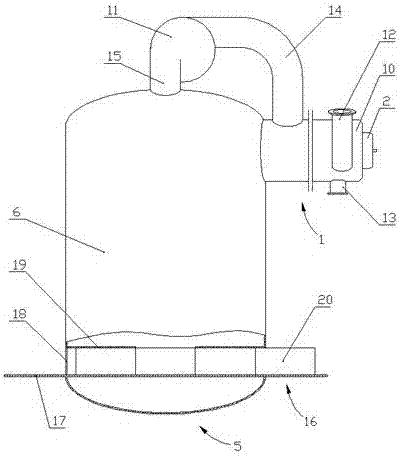
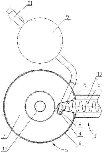
[0020] like Figure 1-2 As shown, this embodiment is a sludge dewatering device, including a conveying mechanism 1, and the conveying mechanism 1 includes an auger 2. The diameter of the end of the auger 2 is gradually reduced to form an extruding part 3, and the end of the extruding part 3 is arranged There are sludge nozzles4.

[0021] The conveying mechanism 1 is connected with a sludge rolling mechanism 5. The sludge rolling mechanism 5 includes a cylindrical shell 6. The extruding part 3 extends into the inside of the shell 6. The projection of the axis of the sludge nozzle 4 is located on the projection of the shell 6. on the eccentric chord; the inside of the housing 6 is provided with a spiral slideway 7, and the top of the spiral slideway 7 is located below the sludge nozzle 4 and close to the sludge nozzle 4.

...


PUM


Abstract

The invention discloses a sludge dewatering device which comprises a conveying mechanism, wherein the conveying mechanism comprises an auger; the diameter of the end part of the auger gradually shrinks to form an extraction part; a sludge nozzle is arranged at the end part of theextraction part; the conveying mechanism is connected with a sludge ball rolling mechanism; the sludge ball rolling mechanism comprises a cylindrical shell; theextraction part stretches into the shell; the projection of an axis of the sludge nozzle is located on an eccentric chord of the projection of the shell; a hot air nozzle is arranged on the side wall of the shell; an outlet of the hot air nozzle is located below the sludge nozzle; a heating cavity connected with the shell is encircled at the outer part of the auger; an air blower 1 is arranged at the top end of the shell and is connected with an air guide pipe; the air guide pipe 14 is communicated with the heating cavity. The scheme has the beneficial effects that according to the description of the scheme, the structure is simple; the design is reasonable; sludge is dried, smoke of thermal energy equipment for drying the sludge is purified, and germs in the sludge are eliminated.

Description

technical field [0001] The invention relates to sludge treatment equipment, in particular to a sludge dewatering device. Background technique [0002] Sludge is a product in the process of sewage treatment. Due to the high moisture content of sludge (generally 96%-99.8%), it is bulky, which brings great difficulties to transportation, treatment and utilization; Its volume has a great influence, for example, when the water content of the sludge is reduced from 99% to 96%, its volume can be reduced to 1 / 4 of the original volume, and when the water content is reduced from 95% to 90%, the volume is reduced by half; 1m3 The domestic sewage sludge with a water content of 95% or more has a volume of about 1000L. As the water content decreases, its volume decreases rapidly. If the water content drops to 85%, its volume is only 1 / 3 of the original (about 333L); 65%, its volume is only 1 / 7 of the original (about 143L); further reduced to 20%, only 1 / 16 (about 62.5L) remains. The cur...

Claims


Application Information

Patent Timeline
IPC IPC(8): C02F11/12F23G7/00
CPCC02F11/13F23G7/001F23G2209/12
Inventor 李振平陈位锁李笑然
Owner 北控水务建设发展有限公司
Learn More