


Quick Research
Generate reliable direction feasibility study reports for your R&D in just a few steps.

Technical Q&A
Discover and master advanced knowledge NOW. Basics, ideas, possibilities, all at once.

Find Solutions
As an expert in R&D theories, this can generate solutions to your technical problems instantly.

Evaluate Feasibility
Analyze your overall solution with one click, know your potential R&D risks in advance.

Monitor Landscape
Get weekly tech updates, stay abreast of the latest tech innovations and key insights.
Full-automatic intelligent following luggage car
A technology of intelligent following and luggage carts, which is applied in the direction of motor vehicles, trolleys, multi-axis trolleys, etc., can solve the problems of inconvenient use, avoid tediousness and effort, and improve the accuracy of positioning and ranging
- Summary
- Abstract
- Description
- Claims
- Application Information
AI Technical Summary
Problems solved by technology
Method used
Image

Examples
Embodiment 1
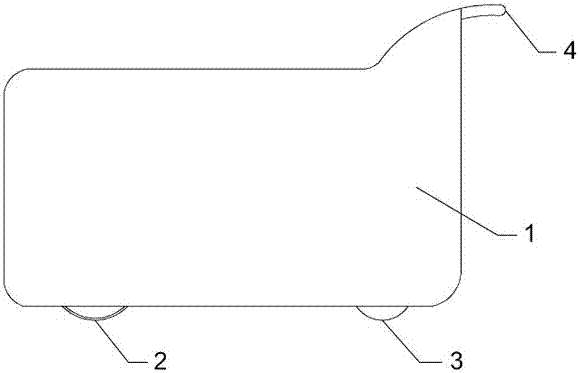
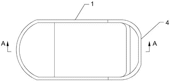
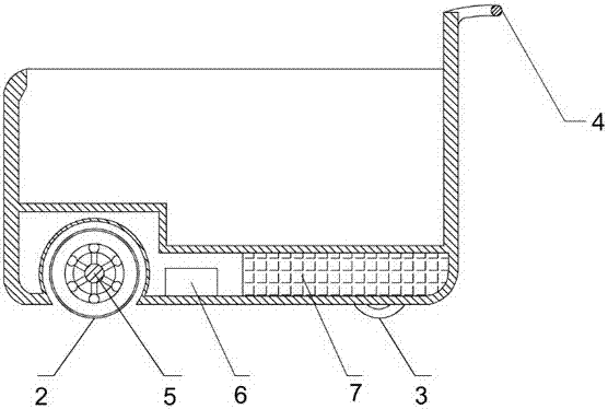
[0029] Attached Figure 1-3 , Picture 9 As shown, a fully automatic and intelligent luggage trolley is used to realize the following operation of the luggage trolley according to a predetermined trajectory. It includes a luggage trolley body and a follow-up system. The luggage trolley body includes a body 1 and is arranged in a triangle underneath the body 1 Layout of the roller device, the roller device consists of a driving wheel 2 arranged in the front of the lower part of the car body 1 and driven wheels 3 symmetrically arranged on both sides of the lower rear of the car body 1, the driving wheel 2 through the universal drive shaft 5. For driving, the lower part of the vehicle body 1 is also provided with a front wheel cavity 21 for accommodating the driving wheel 2 and a rear wheel cavity 31 for accommodating the driven wheel 3, and the universal drive shaft 5 is connected to the drive provided inside the vehicle body 1. Mechanism connection; the follow-up system includes ...
Embodiment 2
[0031] In order to further optimize and illustrate the present invention, on the basis of embodiment 1, combined with Figure 1-9 As shown, the universal drive shaft 5 includes a shaft body 51, a drum-shaped steering body fixed or integrally connected with the shaft body 51, and a plurality of steering rolling grooves 53 are provided in parallel along the direction of the shaft body 51. A steering ball 52 is installed in each of the steering rolling grooves 53; the driving wheel 2 includes two parts, a tire and a hub, and the hub is nested and clamped by the balls 52. The universal drive shaft 5 is arranged in a drum shape and the steering ball 52 installed in the steering roll groove 53 is used to cooperate with the wheel hub, which not only realizes the universal rotation of the universal drive shaft 5 and the wheel hub, but also realizes the universal drive shaft 5 Rigid transmission of torsion in the direction of rotation.
[0032] In this embodiment, both sides of the hub n...
PUM
 Abstract
Description
Claims
Application Information
 - R&D Engineer
- R&D Manager
- IP Professional
- Industry Leading Data Capabilities
- Powerful AI technology
- Patent DNA Extraction
Browse by: Latest US Patents, China's latest patents, Technical Efficacy Thesaurus, Application Domain, Technology Topic, Popular Technical Reports.
© 2024 PatSnap. All rights reserved.Legal|Privacy policy|Modern Slavery Act Transparency Statement|Sitemap|About US| Contact US: help@patsnap.com